Eureka AIR delivers breakthrough ideas for toughest innovation challenges, trusted by R&D personnel around the world.

Selectable lethality warhead patterned hole fragmentation insert sleeves

a technology of patterned hole and insert sleeves, which is applied in the direction of fall bombs, ammunition projectiles, weapons, etc., can solve the problems of increasing logistics and supply, and increasing the cost of materials

Inactive Publication Date: 2012-09-25
UNITED STATES OF AMERICA THE AS REPRESENTED BY THE SEC OF THE ARMY
View PDF6 Cites 13 Cited by
  • Summary
  • Abstract
  • Description
  • Claims
  • Application Information

AI Technical Summary

Benefits of technology

[0007]The dynamically configurable controlled fragmentation insert mechanism of this invention includes an assembly of three or more sleeves that fit inside the shell casing. The innermost sleeve contains the explosive material and eliminates voids that could adversely affect performance or even initiate premature detonation during launch. The explosive material comprises, for example, LX-14, OCTOL, hand packed C-4, or any other solid explosive that might be machined, cast, or hand-packed to fit snugly within the inside of the innermost sleeve. The dynamically selectable hole pattern is made up of two or more additional sleeves, each perforated with a unique pattern of holes. Each sleeve is designed to fit inside the next. The individual sleeves can move independently of one another and a simple pinning mechanism holds the parts in place for a selected configuration. The warfighter can realign the insert sleeves by manipulating the fuze assembly to create different geometric patterns of holes, each designed to engage a different target set with optimally sized fragments. The insert pattern of holes creates individual geometric shapes that focus the explosive energy released upon detonation to generate multiple high-velocity jets. The jets cut into the steel shell casing in the predefined areas that correlate to the through-holes in the aligned patterned sleeves. This solution makes efficient use of the high velocity radial expansion of the shell initiated upon detonation. The selectable pattern of insert sleeve holes focuses the explosive energy and forces the shell body to break up in a predictable fashion. Realigning the insert sleeves changes the through-hole pattern to produce different fragment sizes and mass distributions. The aligned through-holes focus the explosive energy at specific points on the inside of the shell casing and the blocked holes limit the expansion, allowing warhead designers to precisely control the fragment geometry. To defeat light armored vehicles or other materiel targets, the warfighter can deploy the warhead without changing the default mechanical offset of the insert sleeve hole pattern to produce larger fragments with greater penetrating power, or to engage enemy troops, the warfighter can easily “dial in” the hole pattern through the fuze assembly to otherwise configure a much larger number of smaller, lighter fragments. Now, the warfighter can instantaneously configure one warhead in the field to engage multiple target types. The invention functions by focusing the explosive energy released upon detonation into a series of high velocity jets, much like the action of shaped charges. The jets cut into the shell body breaking it into smaller pieces. The alignment of the patterned sleeves, the number of sleeves, the pattern / frequency and size of the holes, and the geometry of the holes can be modified to produce different combinations of large and small sized fragments. The sleeve can be made out of a variety of low-cost, easily machined materials including metals and plastics. This new patterned hole insert sleeve assembly addresses the downfalls of the existing fragmentation enhancement methods in the following ways:
[0008]1. The insert sleeve assembly requires no modifications to the existing projectile body and this novel solution easily conforms to both cylindrical and non-cylindrical shell casings including tapered mortar bodies and round grenades.
[0009]2. Manufacturers can mass produce the simple patterned hole insert sleeves for low cost using casting, stamping, or rolling methods and inexpensive materials including metals and plastics. The basic patterned hole fragmentation design calls for fabricators to manufacture just three simple insert sleeves with easily mass produced tolerances compared to other fragmentation insert designs that require a multitude of intricate machined parts with high tolerance specifications. To produce the patterned hole fragmentation inserts, makers can simply punch holes in sheet metal and then roll the sheets up into sleeves.

Problems solved by technology

This obligatory approach creates a burden on logistics and supply.
Additionally, existing artillery and mortars produce limited lethality depending upon the grade of steel used in their shells.
One significant obstacle to mission success is that a fragmentation warhead designed to defeat personnel is not generally effective against materiel targets including trucks and light armored vehicles, where fragments of relatively greater size and mass are required.
This results in a burden on logistics and supply.
Existing artillery and mortars produce limited lethality depending upon the grade of steel used in their shells.
While these techniques can improve lethality, each traditional approach presents its own problems.
Manufacturing HF steel involves a time consuming and costly heat treatment process.
Scoring the casing weakens the shell's structural rigidity presenting potential problems related to survivability.
Adding preformed fragments helps to assure that the warhead delivers a few optimally sized fragments but fails to enhance the fragmentation of the existing shell casing.
Multiple detonator initiation schemes are very complicated and the additional detonators reduce the amount of space available for high explosive material.

Method used


Image

  • Selectable lethality warhead patterned hole fragmentation insert sleeves
  • Selectable lethality warhead patterned hole fragmentation insert sleeves
  • Selectable lethality warhead patterned hole fragmentation insert sleeves

Examples


Embodiment Construction

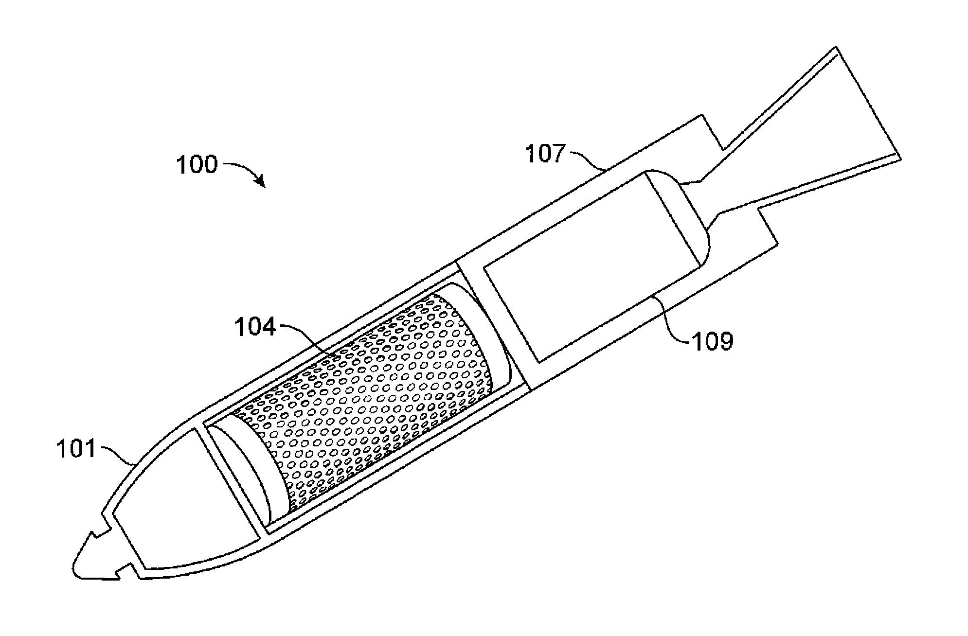
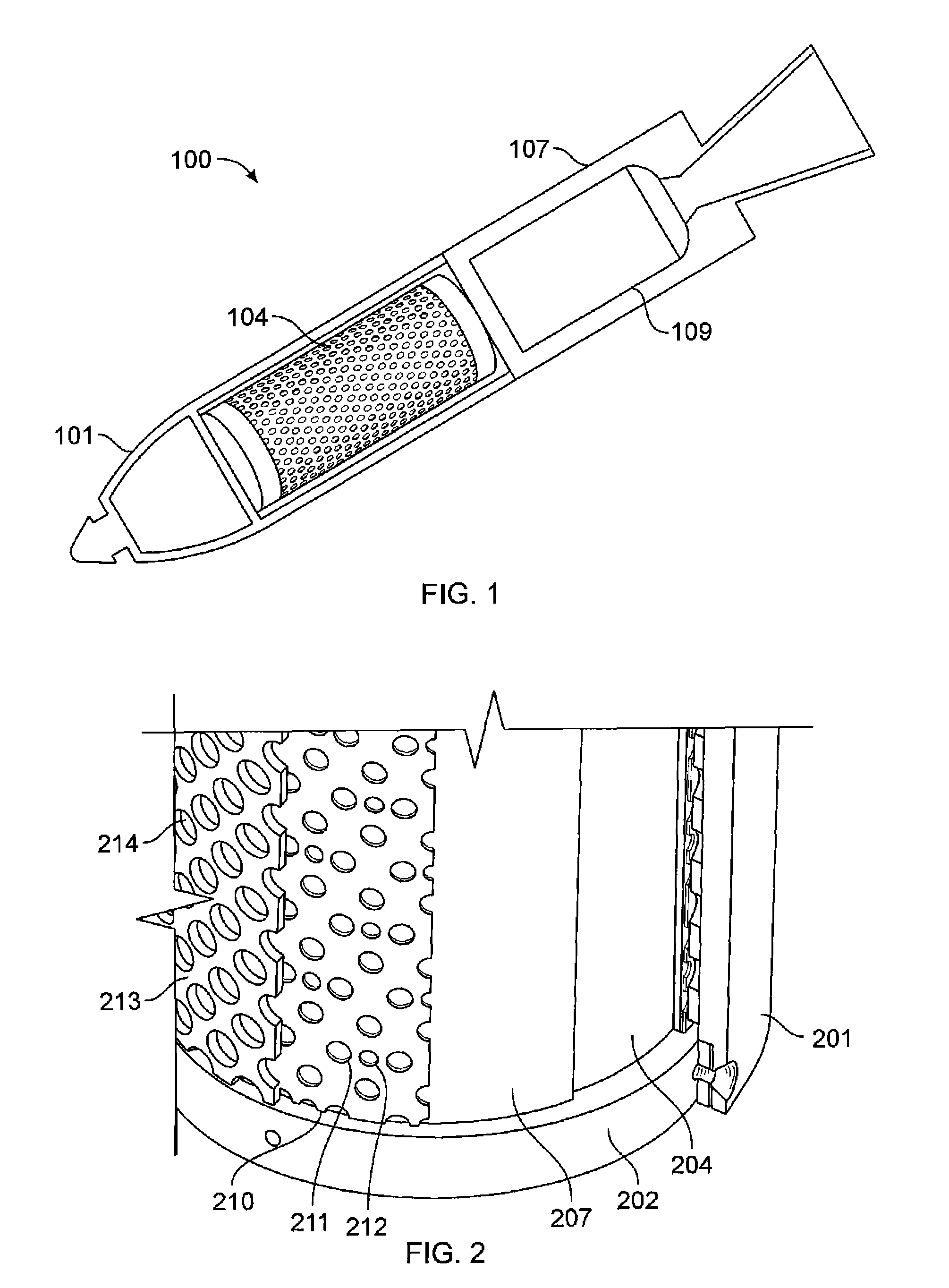
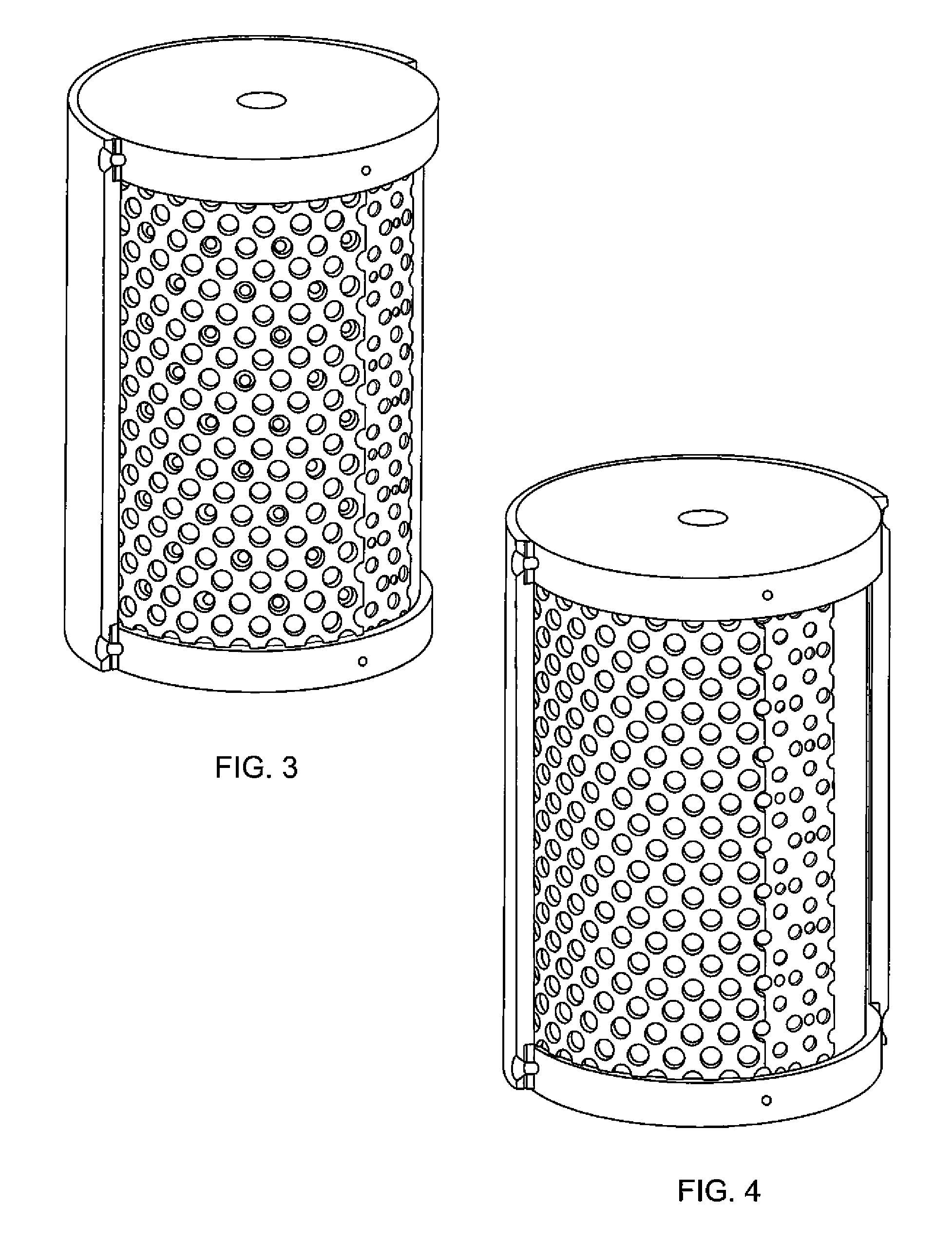
[0027]In FIG. 1, there is shown a subject round 100 which might employ the invention. Round 100 has a fore section 101, an aft section 107, and a propulsion means 109. Behind the fore section is a warhead 104 section, which warhead includes this invention. Warhead 104 is shown in enlarged partial cutaway views in FIG. 2. A pair of circular shaped base elements 202 serve as bookends, in between which are mounted several cylindrically shaped elements. These begin innermost with a more or less solid cylindrically shaped (explosive billet), main charge 204. Next surrounding the main charge 204 is a more or less hollow cylindrical sheet metal shield 207(an explosive containment sleeve). Next surrounding the metal shield 207 is a more or less hollow cylindrical sheet metal inner sleeve 210. Inner sleeve has a first pattern of relatively small holes 212 punched there through (which holes may be of equal size to one another, or not), and a second pattern of relatively larger holes 212 punch...


PUM


Abstract

The dynamically configurable controlled fragmentation insert mechanism of this invention includes an assembly of three or more sleeves with differing through hole patterns thereon, that fit inside the shell casing. The individual sleeves can move independently of one another and a simple pinning mechanism holds the parts in place for a selected configuration. The warfighter can realign the insert sleeves by to create different geometric patterns of holes, each designed to engage a different target set with optimally sized fragments. The aligned patterns of holes creates individual geometric shapes that focus high-velocity jets to cut into the steel shell casing to correlate to the through-holes in the aligned patterned sleeves. Realigning the insert sleeves changes the through-hole pattern to produce different fragment sizes and mass distributions. To defeat light armored vehicles for instance, a warfighter can deploy a sleeve hole pattern to produce larger fragments with greater penetrating power, while to engage enemy troops for instance, a warfighter can “dial in” another hole pattern through the fuze assembly to otherwise produce a much larger number of smaller, lighter fragments.

Description

GOVERNMENT INTEREST[0001]The inventions described herein may be made, used, or licensed by or for the U. S. Government for U. S. Government purposes.BACKGROUND OF INVENTION[0002]To destroy a specific target of a defined armor protection and size, a given fragmentation warhead must deliver a large number of optimally sized fragments within an effective lethal area. To combat multiple threat scenarios, the U.S. military must maintain supplies of several different fragmentation warheads, each type adapted for use against a particular target set. This obligatory approach creates a burden on logistics and supply. Additionally, existing artillery and mortars produce limited lethality depending upon the grade of steel used in their shells. Making more lethal, multi-purpose munitions available to the military would result in significant inventory reductions and cost savings.[0003]The U.S. military employs fragmentation warheads against a wide variety of targets ranging from personnel, radar...

Claims


Application Information

Patent Timeline
IPC IPC(8): F42B12/22
CPCF42B12/24
Inventor HSIEH, HENRYROTTINGER, PETERFONG, RICHARD
Owner UNITED STATES OF AMERICA THE AS REPRESENTED BY THE SEC OF THE ARMY
Why Eureka
Eureka Blog
Learn More