Oven

a technology for ovens and ovens, applied in the field of ovens, can solve the problems of inability to clearly capture the inside of the cooking compartment, and achieve the effect of preventing the temperature of the camera from increasing

Active Publication Date: 2018-03-01
SAMSUNG ELECTRONICS CO LTD
View PDF5 Cites 40 Cited by
  • Summary
  • Abstract
  • Description
  • Claims
  • Application Information

AI Technical Summary

Benefits of technology

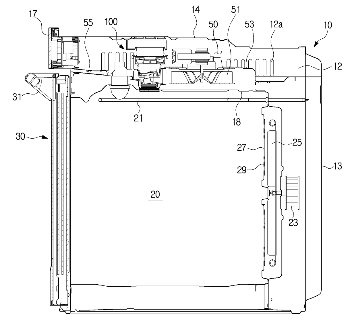
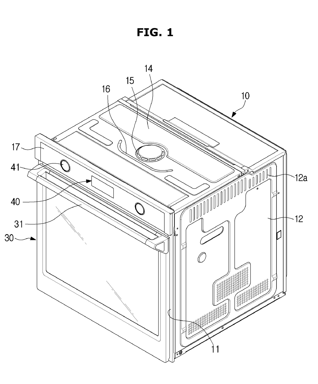
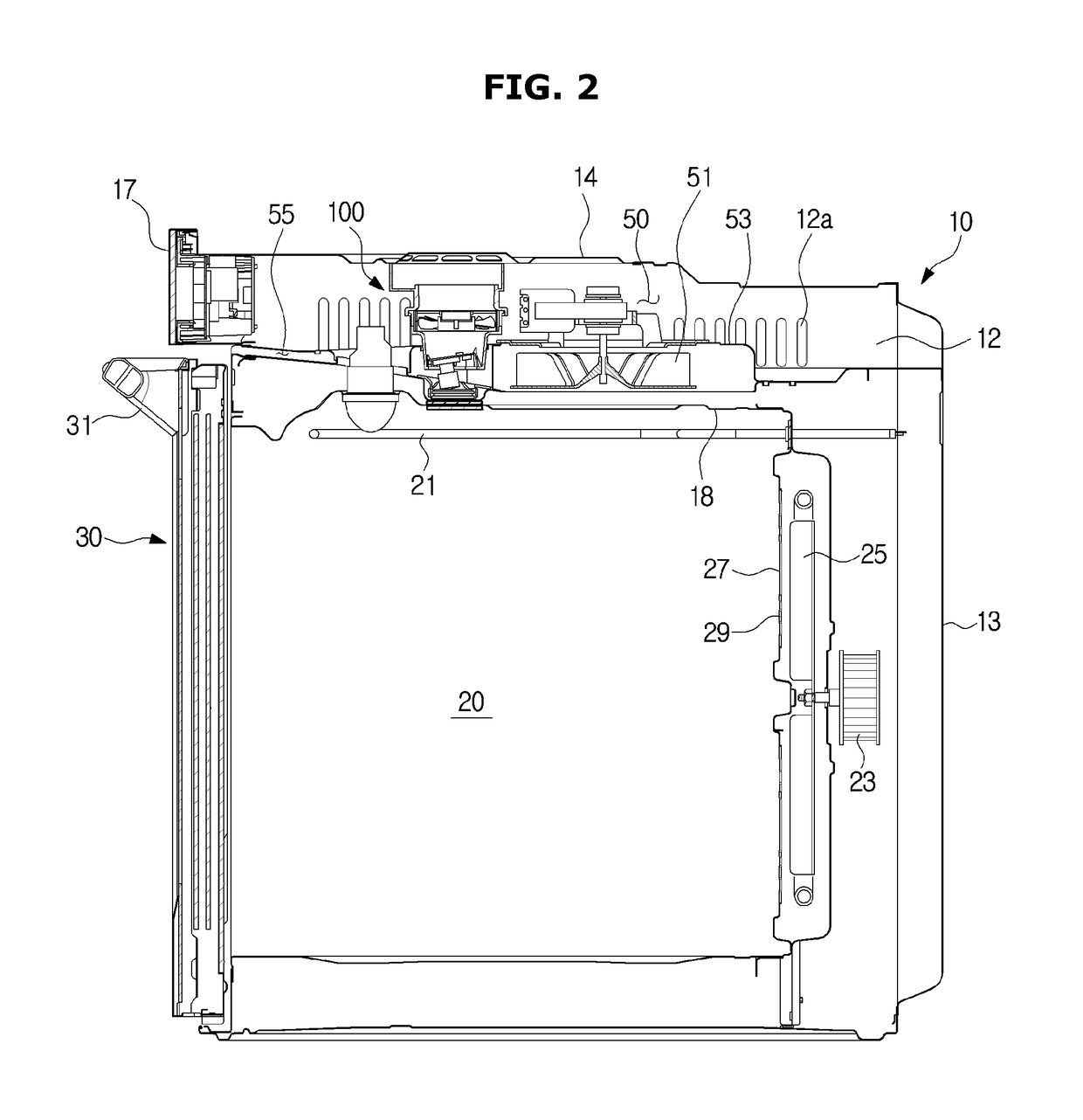
[0009]Therefore, it is an aspect of the present disclosure to provide an oven which includes a camera disposed above a cooking compartment to clearly capture an inside of the cooking compartment and has a structure which cools the camera to prevent a temperature of the camera from being increased due to heat generated in the cooking compartment.
[0012]An inlet may be provided at an upper portion of the main body and be configured to suction the external air to cool the camera, and a rib may be provided around the inlet and configured to prevent water from passing through the inlet.
[0017]A blocking member configured to block a part of the exhaust duct may be provided between the camera and the electrical component chamber cooling fan to prevent air discharged into the exhaust duct from contacting with the camera.
[0018]The blocking member may support the exhaust duct to prevent sagging of the exhaust duct.
[0041]At least one glass may be provided under the camera and configured to allow the camera to capture the inside of the cooking compartment and block transmission of heat in the cooking compartment to the camera.
[0043]The glass may include a first glass provided at a ceiling of the cooking compartment so that the camera captures the inside of the cooking compartment and configured to block the transmission of the heat in the cooking compartment to the camera, and a second glass provided between the camera and the first glass and configured to additionally block the transmission of heat to the camera.

Problems solved by technology

However, when the inside of the cooking compartment is captured by the external camera, phase diffuse reflection is generated due to a property of a glass mounted on a door of the oven, and thus the inside of the cooking compartment may not be clearly captured.

Method used


Image

  • Oven
  • Oven
  • Oven

Examples


Embodiment Construction

[0070]Embodiments described in this specification and configurations illustrated in drawings are only exemplary examples of the disclosed disclosure. It should be understood that the disclosure includes various modifications that may replace the embodiments and drawings at the time of filing of this application.

[0071]Like reference numerals of each drawing of the specification denote substantially similar components or elements.

[0072]Also, the terms used in the following description are intended to merely describe specific embodiments and are not intended to limit and / or restrict the disclosed disclosure. An expression used in the singular encompasses the expression of the plural. In the present specification, it should be understood that terms such as “including,”“having,” and “comprising” are intended to indicate the existence of features, numbers, steps, actions, components, parts, or combinations thereof disclosed in the specification, and are not intended to preclude the possib...


PUM


Abstract

An oven including a camera disposed above a cooking compartment to clearly capture an inside of the cooking compartment, and having a structure which cools the camera to prevent a temperature of the camera from being increased due to heat generated in the cooking compartment. The oven includes the camera provided above the cooking compartment and configured to capture the inside of the cooking compartment, a camera cooling fan disposed above the camera and configured to cool the camera by suctioning external air, a first glass provided at a ceiling of the cooking compartment so that the camera captures the inside of the cooking compartment and configured to block transmission of heat in the cooking compartment to the camera, and a second glass provided between the camera and the first glass and configured to block transmission of heat to the camera.

Description

CROSS-REFERENCE TO RELATED APPLICATION[0001]This application claims the benefit of Korean Patent Application Nos. 10-2016-0112778 and 10-2017-0016282, filed on Sep. 1, 2016 and Feb. 6, 2017, respectively in the Korean Intellectual Property Office, the disclosure of which is incorporated herein by reference.BACKGROUND1. Field[0002]Embodiments of the present disclosure relate to an oven including a camera provided above a cooking compartment to capture an inside of the cooking compartment.2. Description of the Related Art[0003]Generally, an oven is a device for cooking foods and includes a cooking compartment, a heating device applying heat to the cooking compartment, and a circulation fan circulating the heat generated by the heating device in the cooking compartment.[0004]The oven, which is a device for sealing, heating, and cooking an object to be cooked, may be generally classified into an electric-type oven, a gas-type oven, and an electronic-type oven depending on a heat source....

Claims


Application Information

Patent Timeline
Patent Type & Authority Applications(United States)
IPC IPC(8): F24C15/00F24C7/08F24C7/04F24C15/32F27D21/02
CPCF24C15/008F24C7/081F27D2021/026F24C15/322F27D21/02F24C7/04A47J37/0623A47J37/0664F24C7/046F24C7/085F24C15/006
Inventor JANG, HYEONG JINLEE, SANG-JINLEE, JUNG HAKKWON, MYOUNG KEUNPARK, SANG JUNSEO, EUNG RYEOLSUNG, HAN JUN
Owner SAMSUNG ELECTRONICS CO LTD
Why Eureka
Try Eureka