Turbine blade dual channel cooling system

a cooling system and turbine blade technology, applied in the field of turbine blades, can solve the problems of reducing the useful life affecting the efficiency of the turbine blade, so as to prevent temperature overage and blade damage

Inactive Publication Date: 2010-09-09
SIEMENS ENERGY INC
View PDF18 Cites 37 Cited by
  • Summary
  • Abstract
  • Description
  • Claims
  • Application Information

AI Technical Summary

Benefits of technology

[0004]This invention relates to a turbine blade cooling system for turbine blades used in turbine engines. In particular, the turbine blade cooling system includes a cavity positioned between two or more walls forming a housing of the turbine blade. The cooling system may be formed from first and second cooling channels positioned in internal aspects of the blade and in communication with first and second tip cooling channels, respectively. The first and second tip cooling channels provide cooling to the tip aspects of the turbine blade to prevent temperature overages and blade damage.

Problems solved by technology

In addition, turbine blades often contain cooling systems for prolonging the life of the blades and reducing the likelihood of failure as a result of excessive temperatures.
However, centrifugal forces and air flow at boundary layers often prevent some areas of the turbine blade from being adequately cooled, which results in the formation of localized hot spots.
Localized hot spots, depending on their location, can reduce the useful life of a turbine blade and can damage a turbine blade to an extent necessitating replacement of the blade.

Method used


Image

  • Turbine blade dual channel cooling system
  • Turbine blade dual channel cooling system
  • Turbine blade dual channel cooling system

Examples


Embodiment Construction

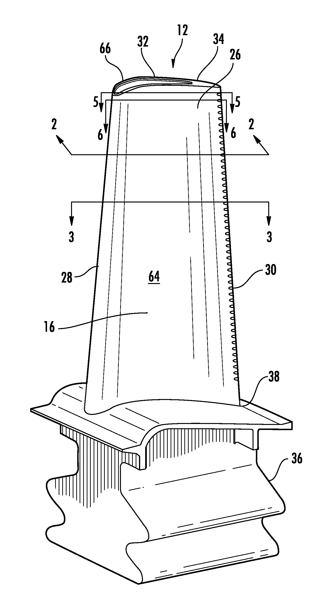
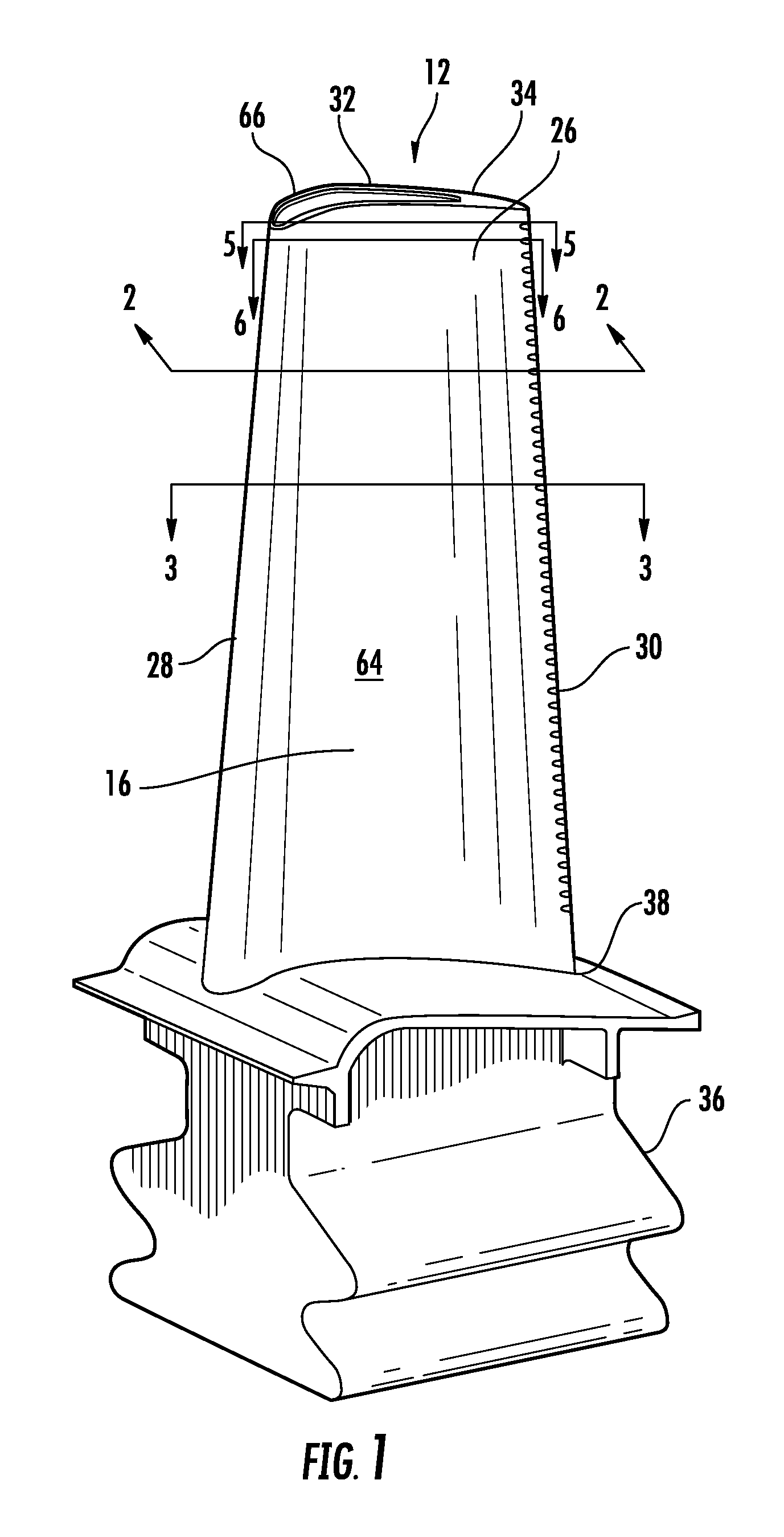
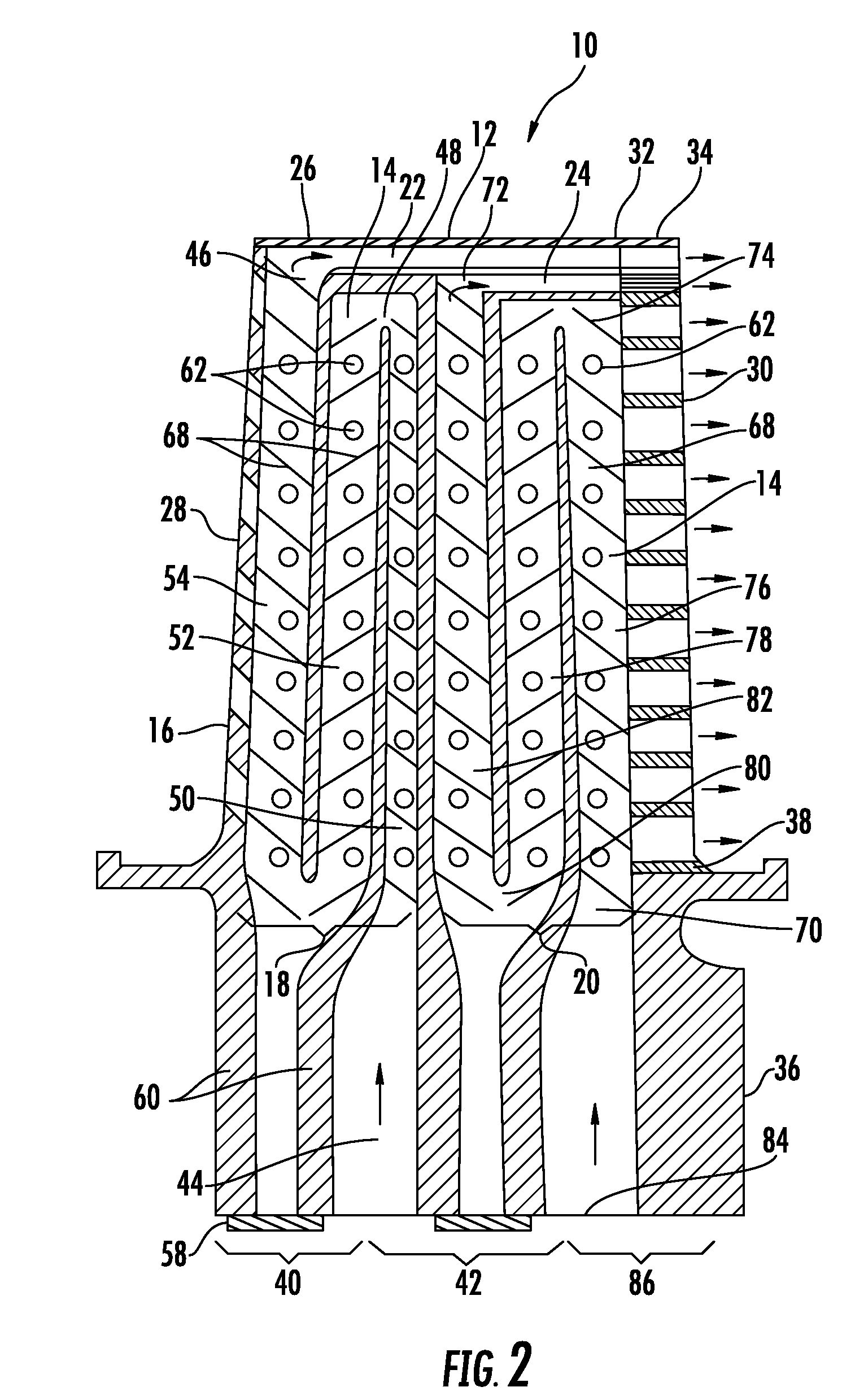
[0022]As shown in FIGS. 1-6, this invention is directed to a turbine blade cooling system 10 for turbine blades 12 used in turbine engines. In particular, the turbine blade cooling system 10 includes a cavity 14, as shown in FIGS. 2 and 3, positioned between two or more walls forming a housing 16 of the turbine blade 12. The cooling system 10 may be formed from first and second cooling channels 18, 20 positioned in internal aspects of the blade 12 and in communication with first and second tip cooling channels 22, 24, respectively. The first and second tip cooling channels 22, 24 provide cooling to the tip aspects of the turbine blade 12 to prevent temperature overages and blade damage.

[0023]As shown in FIG. 1, the turbine blade 12 may be formed from a generally elongated blade 26 having the leading edge 28, the trailing edge 30, a tip 32 at a first end 34, a root 36 coupled to the blade 26 at an end 38 generally opposite the first end 34 for supporting the blade 26 and for coupling...


PUM


Abstract

A turbine blade having an internal cooling system with dual serpentine cooling channels in communication with tip cooling channels is disclosed. In at least one embodiment, the cooling system may include first and second tip cooling channels in communication with the first and second serpentine cooling channels, respectively. The first tip cooling channel may extend from the leading edge to the trailing edge and be formed from a first suction side tip cooling channel and a first pressure side tip cooling channel. The second tip cooling channel may extend from a midchord region toward the trailing edge and may be positioned between the pressure and suction sides such that the second tip cooling channel is positioned generally between the first suction side and pressure side tip cooling channels. The first and second tip cooling channels may exhaust cooling fluids through the trailing edge.

Description

FIELD OF THE INVENTION[0001]This invention is directed generally to turbine blades, and more particularly to cooling systems in hollow turbine blades.BACKGROUND[0002]Typically, gas turbine engines include a compressor for compressing air, a combustor for mixing the compressed air with fuel and igniting the mixture, and a turbine blade assembly for producing power. Combustors often operate at high temperatures that may exceed 2,500 degrees Fahrenheit. Typical turbine combustor configurations expose turbine blade assemblies to these high temperatures. As a result, turbine blades must be made of materials capable of withstanding such high temperatures. In addition, turbine blades often contain cooling systems for prolonging the life of the blades and reducing the likelihood of failure as a result of excessive temperatures.[0003]Typically, turbine blades are formed from a root portion at one end and an elongated portion forming a blade that extends outwardly from a platform coupled to t...

Claims


Application Information

Patent Timeline
Patent Type & Authority Applications(United States)
IPC IPC(8): F01D5/18
CPCF01D5/186F05D2260/22141F05D2250/185F01D5/187
Inventor LIANG, GEORGE
Owner SIEMENS ENERGY INC
Why Eureka
Try Eureka