Heat Pipe heat sink

a heat sink and heat pipe technology, applied in the field of heat sinks, can solve the problems of pipe failure, cooling capability decrease, insufficient radiation capability of heat sinks having such configurations, etc., and achieve the effect of preventing the temperature of the heating element from increasing significantly and high cooling capability

Active Publication Date: 2007-08-16
FURUKAWA SKY ALUMINUM CORP
View PDF20 Cites 43 Cited by
  • Summary
  • Abstract
  • Description
  • Claims
  • Application Information

AI Technical Summary

Benefits of technology

[0015] According to the present invention, by allowing the heat to radiate from the heating member to a wide range of the base plate through the heat pipes to equalize the heat in the base plate, it is possible to provide a heat sink configured to maintain high cooling capability and to prevent the temperature of the heating element from increasing significantly, even if the heat sink is inclined in any direction.

Problems solved by technology

However, radiating capability of the heat sink having such the configuration is not always sufficient.
As in the description of JP-A-2002-262583, since heat pipes are commonly embedded in a plurality of heating members, there is a problem in that, although predetermined cooling capability can be obtained when an inclination occurs in a certain direction, the cooling capability decreases when the inclination occurs in a different direction.
This is a fatal problem particularly in the case of the heat sink used in an approximately horizontal state, in which the heat pipes cannot be installed in the inclined state because of a limitation concerning a shape and weight.
Further, if a high temperature section is located in the vicinity of a central portion of a base, there is a defect in that the heat pipes do not work effectively.
Meanwhile, the heat sink using the evaporation-cooling method, in which the working fluid for cooling the device having high heat density is a fluorine-containing compound (for example, trade name “Fluorinert FX-3250”, manufactured by Sumitomo 3M Limited), is expensive because an overall configuration of the heat sink is complex.
However, there is an increasing hesitation in the usage thereof these days, from the viewpoint of preventing environment degradation.
In a case where the heat sink is configured to have a relatively low height so as to be used in train vehicles such as bullet trains, automobiles, or the like, namely, in the case where a length of radiating sections of the heat pipes disposed with the fins is relatively short, there is a disadvantage in that the heat is not discharged sufficiently because effectiveness concerning thermal conductivity from the heat pipes to the radiating fins is insufficient.
Further, in a case where cooling water is used as a cooling fluid, if an ambient temperature in a place where the heat sink having such the configuration is used reaches below 0 (zero) ° C., there is a fear that the cooling water in the heat pipes may be frozen on a radiating section side and not reflow toward a heat-receiving section, so there is a defect in that an essential function of the heat pipes cannot be obtained.
In addition, there is a case where the heat pipes themselves are exposed to the outside on a surface of the base plate, so there is a problem in that the exposed portion is broken because the cooling water therein is frozen during use and transportation.

Method used


Image

  • Heat Pipe heat sink
  • Heat Pipe heat sink
  • Heat Pipe heat sink

Examples


Embodiment Construction

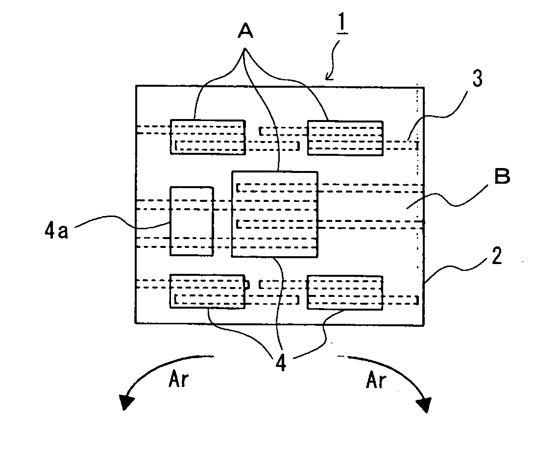
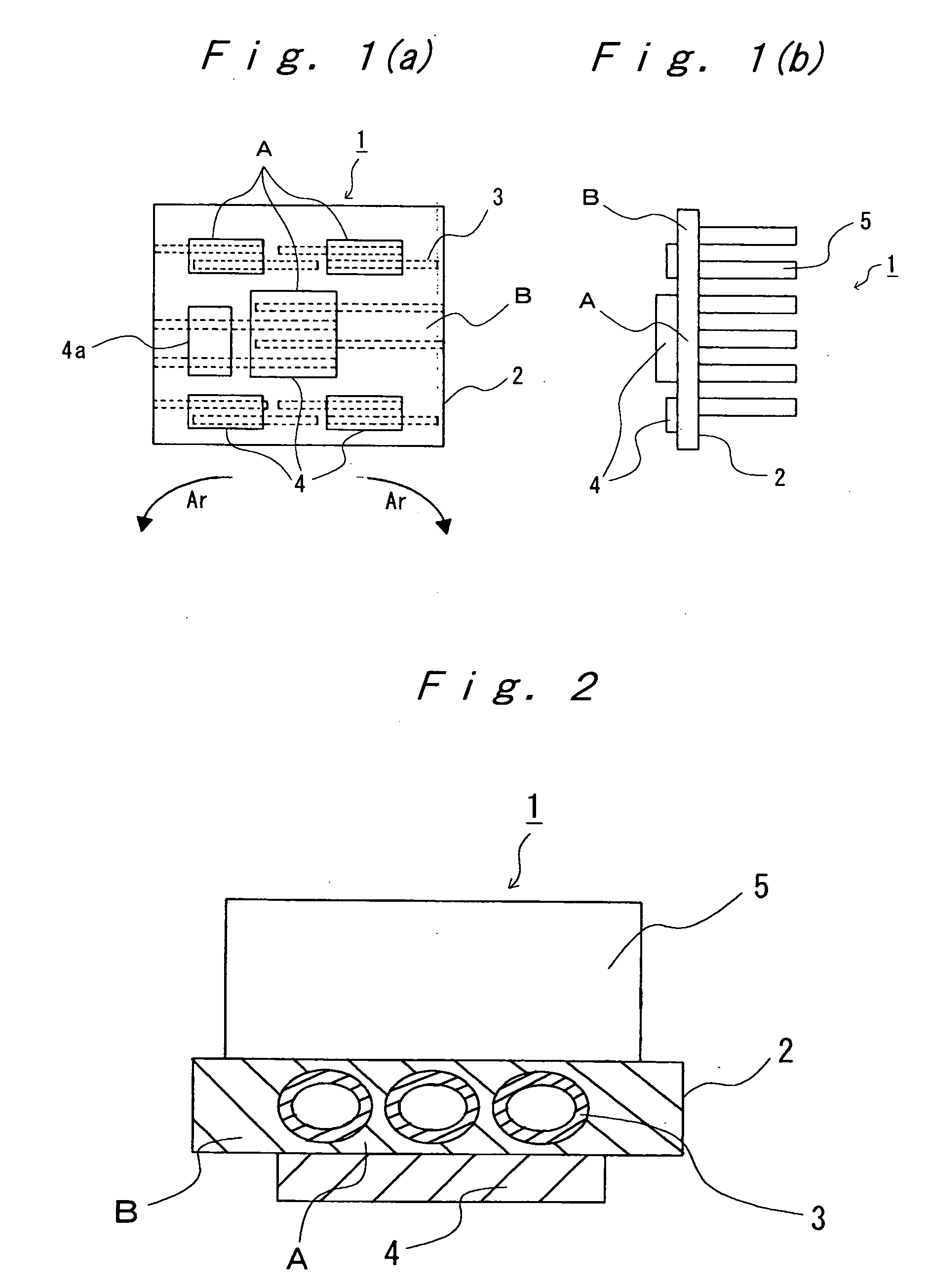
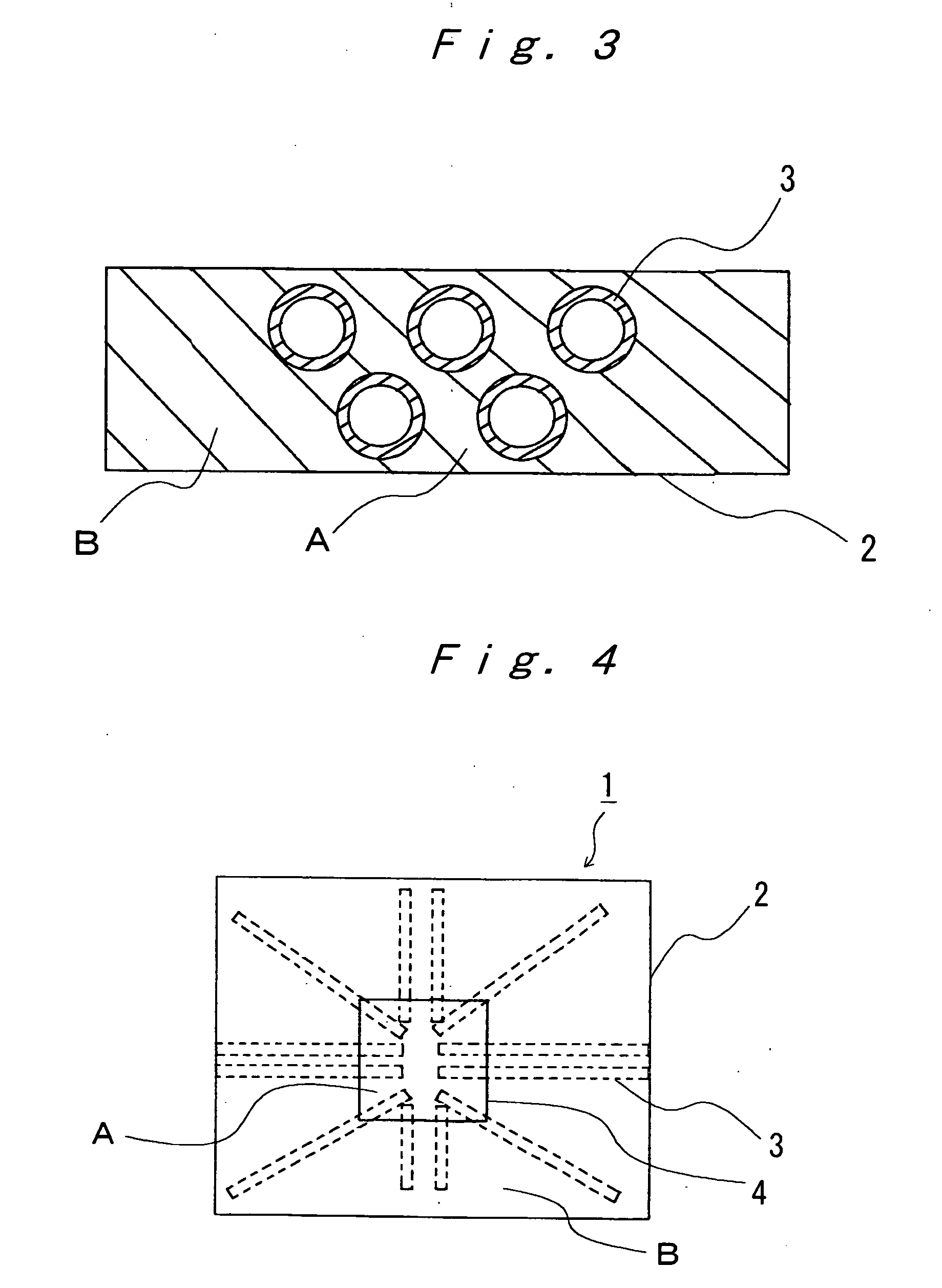
[0023] Preferable and specific embodiments of the heat sink of the present invention will be explained in detail below with reference to FIGS. 1(a) to 5, but the present invention is not limited to embodiments that are shown in the drawings. The same reference symbols are provided to the same components in the drawings, and duplicate explanations will be omitted.

[0024] FIGS. 1(a) and 1(b) each show a first mode of a heat sink of the present invention, which is a fundamental schematic configuration of a comb-shaped heat sink, FIG. 1(a) is a front view viewed from an opposite side of radiating fins thereof, and FIG. 1(b) is a side view thereof.

[0025] Although FIGS. 1(a) and 1(b) each show an example of a case where a base plate 2 is disposed vertically, the base plate 2 may be disposed horizontally. The base plate 2 and each radiating fin 5 may be formed unitarily by an aluminum extrusion method, and needless to say, any of other alternative methods such as a brazing method, a solde...


PUM


Abstract

A heat sink (1), has heat pipes (3) which are disposed in a high temperature section (A) of a base plate (2) on which a heating element (4) is disposed so that the heat pipes (3) extend from the high temperature section (A) to low temperature sections (B) in different directions.

Description

TECHNICAL FIELD [0001] The present invention relates to a heat sink used for cooling heating elements such as electronic components and optical components, and more particularly, to the heat sink disposed in railroad vehicles or automobiles to be used not only in a horizontal state but also in an inclined state. BACKGROUND ART [0002] Up to now, as a heat sink for cooling heating elements such as an IGBT (insulated gate bipolar transistor) used in power electronics, a relatively inexpensive heat sink has been used in many cases, which has a structure in which a base plate having heating members retained on one surface thereof is used, and a plurality of radiating fins are disposed in a comb-shape or a grid-shape on the other surface of the base plate. However, radiating capability of the heat sink having such the configuration is not always sufficient. In particular, in order to enhance cooling capability in a case of effectively cooling semiconductor devices having high heat density...

Claims


Application Information

Patent Timeline
Patent Type & Authority Applications(United States)
IPC IPC(8): H05K7/20
CPCF28D15/0275H01L23/427H01L2924/0002H01L2924/00
Inventor UENO, SEIZOEDA, YOSHIYANAGAMATSU, SHINYA
Owner FURUKAWA SKY ALUMINUM CORP
Why Eureka
Try Eureka