
Fixing device and image forming apparatus

Inactive Publication Date: 2007-04-26
FUJIFILM BUSINESS INNOVATION CORP
View PDF5 Cites 43 Cited by
  • Summary
  • Abstract
  • Description
  • Claims
  • Application Information

AI Technical Summary

Benefits of technology

[0012] A configuration where the process speed is switched over in accordance with the thickness of a recording sheet may be contemplated. Namely, in the case of a thick sheet, the process speed is set to be slower than the case of a thin sheet, so that the quantity of heat captured from the fixing roll by the recording sheet is suppressed, thereby preventing the temperature of the fixing roll from being lowered.
[0011] Recording sheets have different heat capacities depending on the property such as the thickness. Therefore, the quantity of heat that is captured from the fixing belt by a recording sheet during the fixing process is different depending on, for example, the thickness. When compared with the case where sheets are consecutively passed at a process speed (sheet passing speed) and a set temperature that are set with reference to a thin recording sheet (thin sheet), a thick recording sheet (thick sheet) has a heat capacity larger than that of a thin sheet, and the quantity of heat that is used for fixing a toner is reduced. Therefore, there may arise a disadvantage that a fixing failure easily occurs.

Problems solved by technology

However, a conventional fixing device of the two-roll system has a problem in that a sufficient fixing process is hardly performed on a large number of recording sheets that are consecutively fed at high speed.
In a fixing device of the two-roll system, therefore, it is structrally difficult that a heater disposed inside a fixing roll supplies adaptively and sufficiently a quantity of heat corresponding to that which is captured by the recording sheet from the surface of the fixing roll.
As a result, when recording sheets are consecutively fed at high speed to a fixing device of the two-roll system, there arises a disadvantage that the surface temperature of a fixing roll is gradually lowered, and the fixing performance is progressively impaired.
When a thick sheet or the like having a large heat capacity is used as a recording sheet, particularly, a large quantity of heat is captured from the surface of the fixing roll, and hence the reduction of the fixing performance and the temperature droop are increased, with the result that deterioration of the image quality due to a fixing failure occurs.
Therefore, there may arise a disadvantage that a fixing failure easily occurs.
In the configuration where the process speed is switched over in cases of a thin sheet and a thick sheet in this way, however, the operating efficiency of the case of a thick sheet is lower than that of the case of a thin sheet.
When it is configured so that the set temperatures are switched over in accordance with the sheet thickness, however, there is a problem that the switching process requires a time period.
In the case where a thin sheet is switched to a thick sheet, a temperature rise time period that is considerably long elapses before the fixing roll reaches a higher set temperature, because it is difficult to rapidly heat the fixing roll having a large heat capacity.
Consequently, there is a problem that the operating efficiency is inevitably lowered.

Method used


Image

  • Fixing device and image forming apparatus
  • Fixing device and image forming apparatus
  • Fixing device and image forming apparatus

Examples


Embodiment Construction

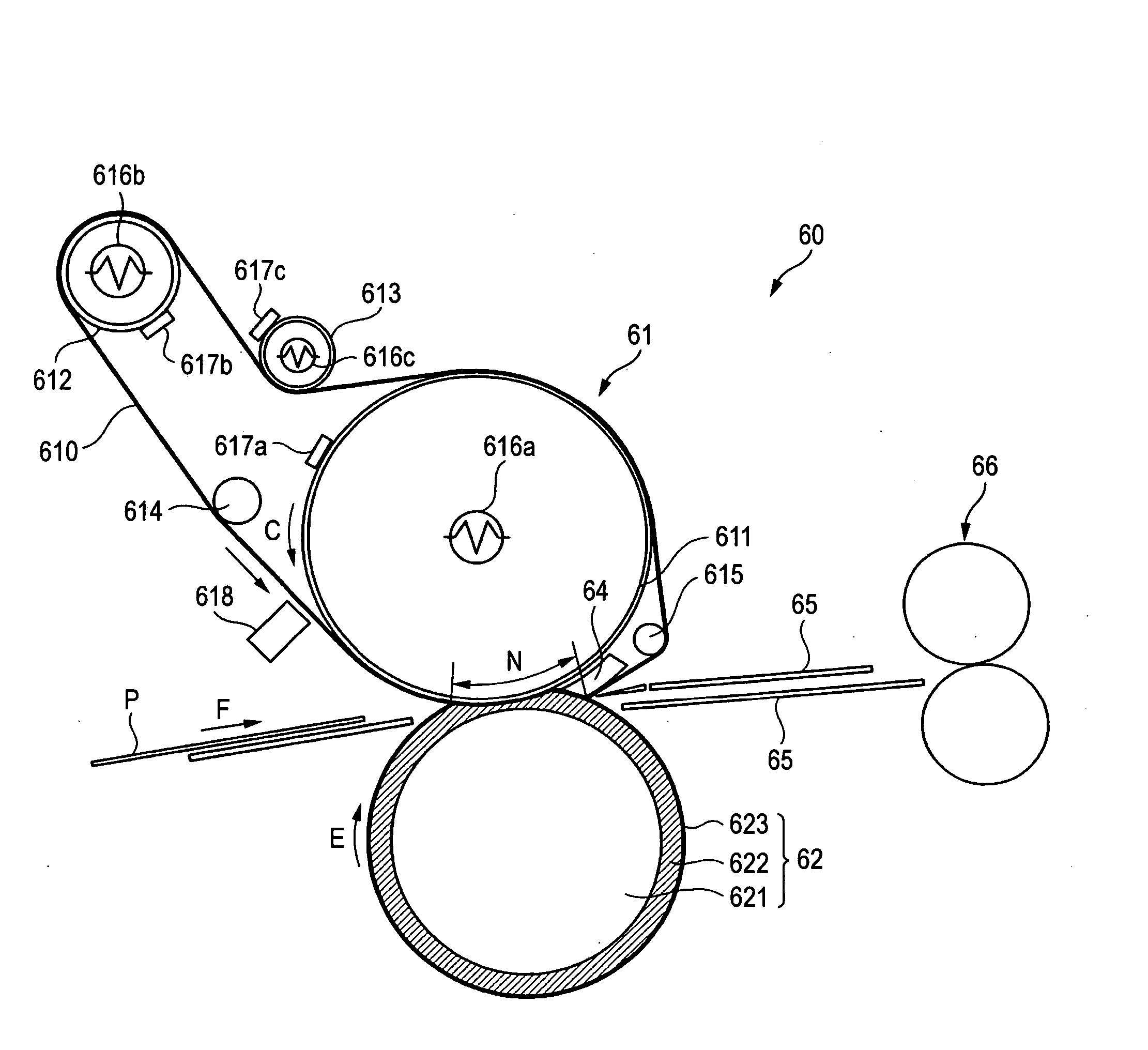
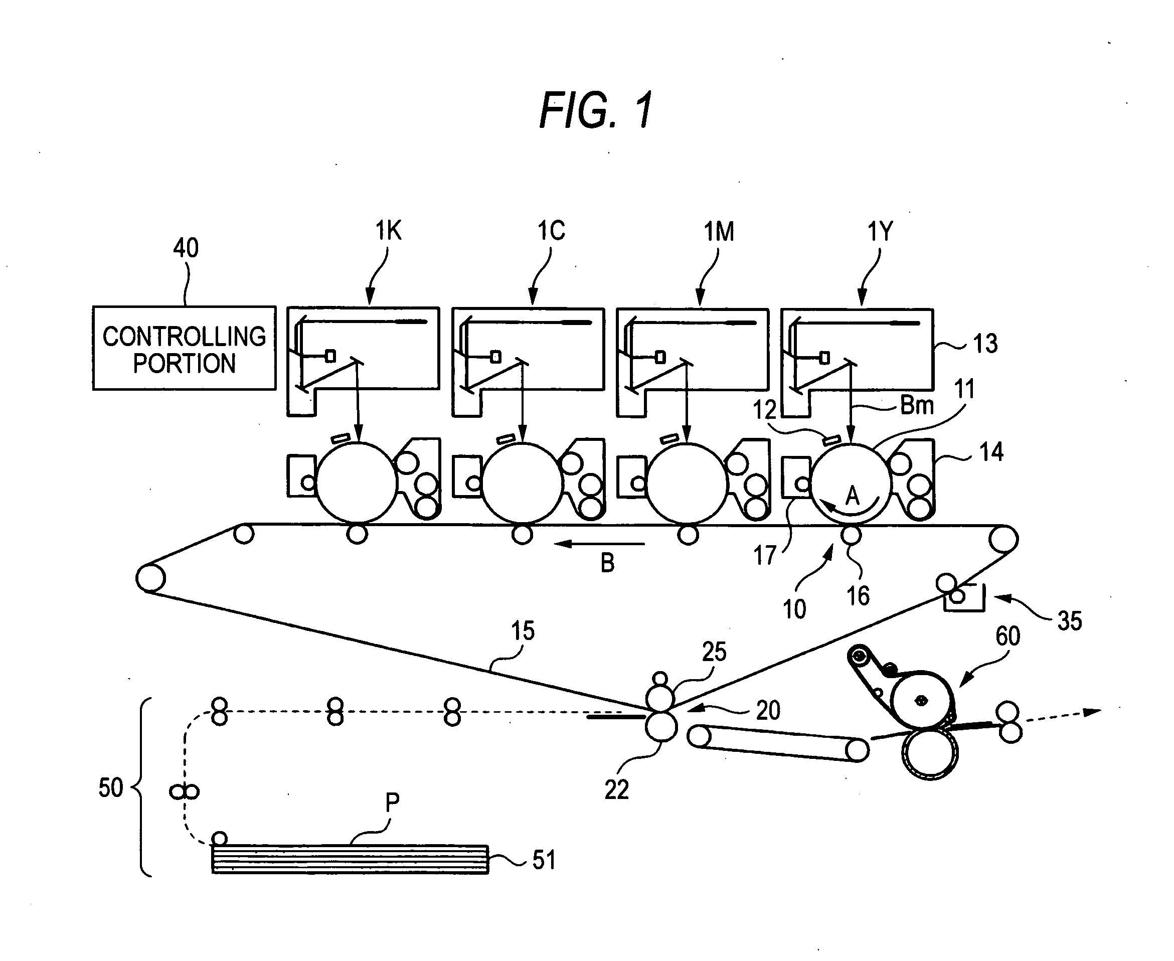
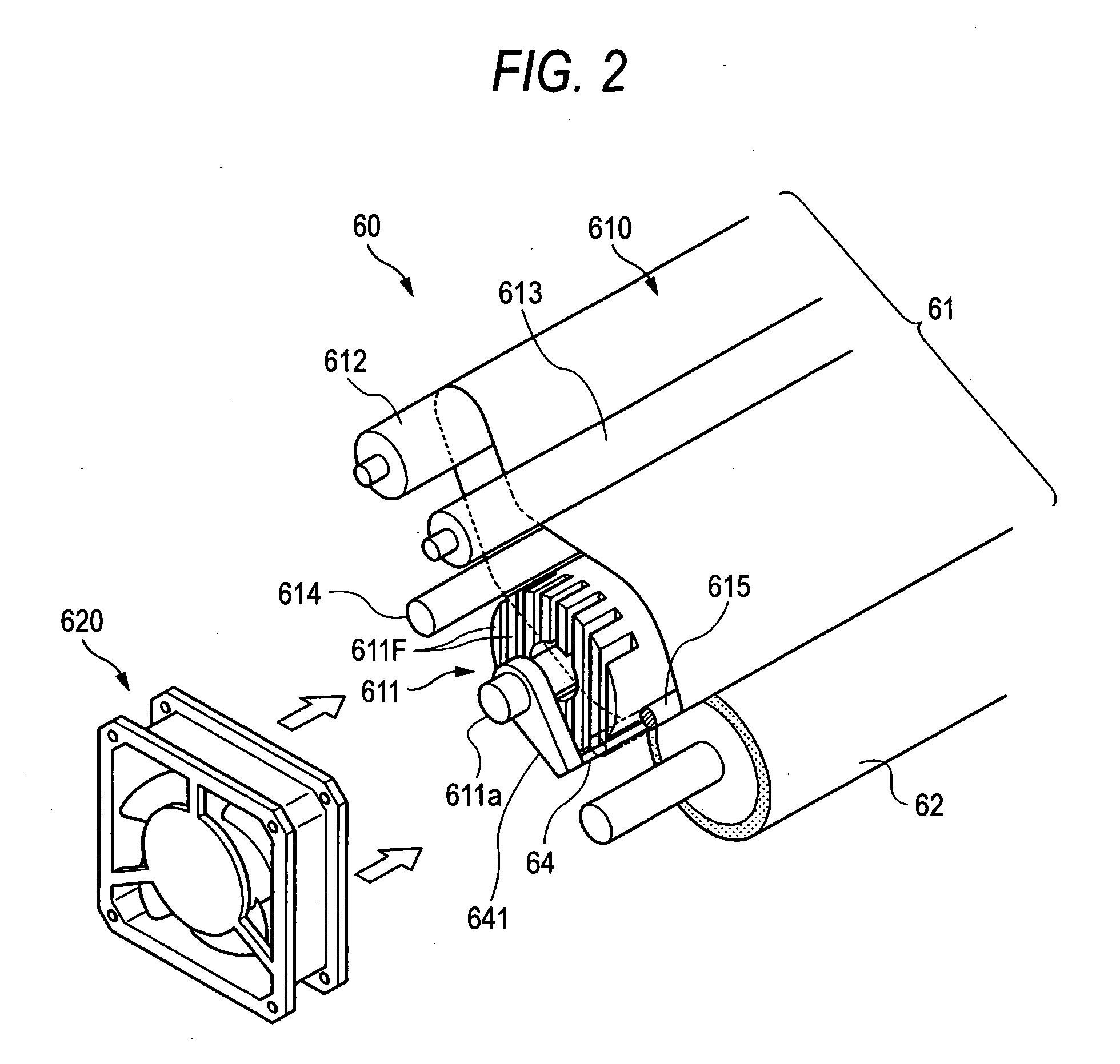
[0026] Hereinafter, an exemplary embodiment of the invention will be described in detail referring to the accompanying drawings. FIG. 1 is a schematic diagram of an image forming apparatus 1 to which the exemplary embodiment is applied.

[0027] The image forming apparatus 1 shown in FIG. 1 is an intermediate-transfer image forming apparatus which is of the so-called tandem type, and includes: plural image forming units 1Y, 1M, 1C, 1K serving as a toner-image forming unit for forming toner images of respective color components by the electrophotographic system; and a primary transfer station 10 which sequentially transfers (primarily transferred) toner images of respective color components formed by the image forming units 1Y, 1M, 1C, 1K, to an intermediate transfer belt 15. The image forming apparatus 1 further includes; a secondary transfer station 20 serving as a transferring unit for collectively transferring (secondarily transferred) superimposed toner images which have been tran...


PUM


Abstract

A fixing device includes: a fixing roll member; a support roll member; a fixing belt member rotated while being mounted on and tensioned by the fixing roll member and the support roll member; a roll heating unit that heats the fixing roll member; a belt heating unit that heats the fixing belt member; a pressing member that is in press contact with a portion of the fixing roll member, around which the fixing belt member is wound, to form a nip portion; and a temperature controlling device that controls and drives the roll heating unit and the belt heating unit. The temperature controlling device controls the fixing roll member and the fixing belt member to be different temperatures.

Description

CROSS-REFERENCE TO RELATED APPLICATION [0001] This application claims priority under 35 USC 119 from Japanese Patent Application No. 2005-308952, the disclosure of which is incorporated by reference herein. BACKGROUND [0002] 1. Technical Field [0003] The present invention relates to a fixing device that is used in an image forming apparatus in which, for example, the electrophotographic system is employed, and more particularly to a fixing device that includes a rotatable belt member. [0004] 2. Related Art [0005] In an image forming apparatus in which the electrophotographic system is used, such as a copier or a printer, image formation is performed in the following manner. First, the surface of a photosensitive member (photosensitive drum), which is formed into, for example, a drum-like shape, is uniformly charged by a charging device. The charged photosensitive drum is scan-exposed to light, which is controlled based on image information, and an electrostatic latent image is forme...

Claims


Application Information

Patent Timeline
IPC IPC(8): G03G15/20
CPCG03G2215/2016G03G2215/2022G03G2215/2032G03G15/2028G03G15/2039
Inventor MIYATA, TOSHIYUKIBABA, MOTOFUMIANDO, CHIKARAYOSHINO, DAISUKE
Owner FUJIFILM BUSINESS INNOVATION CORP
Learn More