Lens assembly

a technology of lens assembly and lens body, applied in the field of lenses, can solve the problems that the conventional lens assembly cannot meet the demand, and achieve the effect of good optical performan

Active Publication Date: 2018-03-01
SINTAI OPTICAL SHENZHEN CO LTD +1
View PDF1 Cites 5 Cited by
  • Summary
  • Abstract
  • Description
  • Claims
  • Application Information

AI Technical Summary

Benefits of technology

[0003]The invention provides a lens assembly to solve the above problems. The lens assembly is provided with characteristics of a short total track length and a small F number, and the lens assembly is still capable of obtaining good optical performance.

Problems solved by technology

However, the conventional lens assembly has been unable to meet demand, and we need another new structure of the lens assembly, and that can meet the miniaturization and large aperture.

Method used


Image

  • Lens assembly
  • Lens assembly
  • Lens assembly

Examples


first embodiment

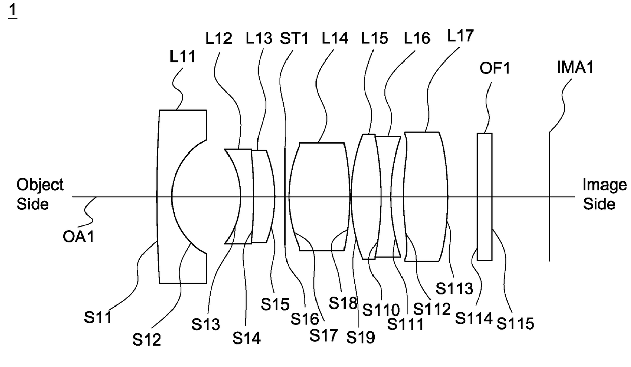
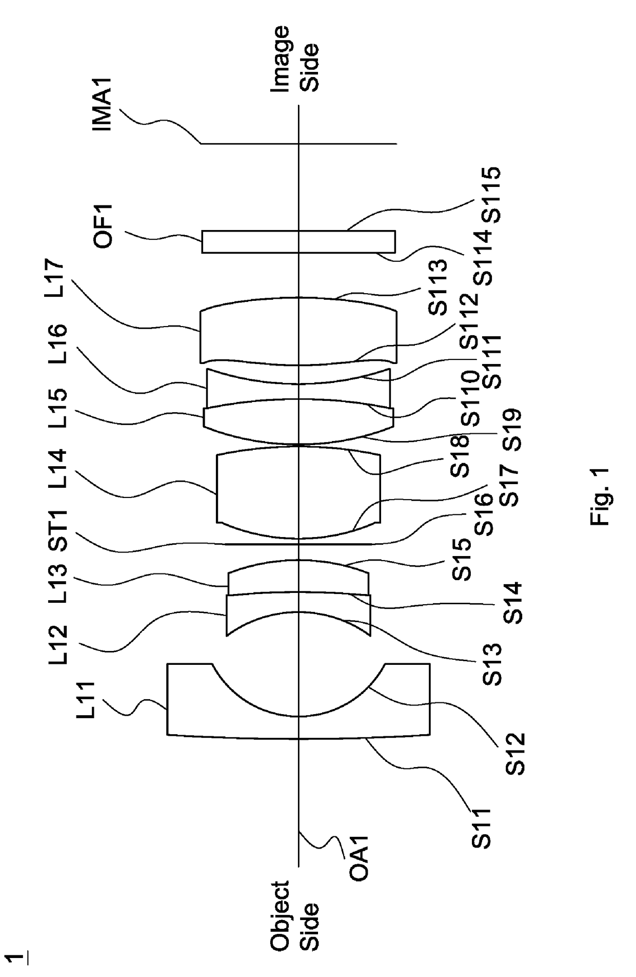
[0026]Referring to FIG. 1, FIG. 1 is a lens layout and optical path diagram of a lens assembly 1 in accordance with the invention. The lens assembly 1, in sequence from an object side to an image side IMA1 along an optical axis OA1, comprises a first lens L11 which is a meniscus lens with negative refractive power and includes a convex surface facing the object side S11; a second lens L12 having negative refractive power and including a concave surface facing the object side S13; a third lens L13 having positive refractive power and including a convex surface facing the image side S15; a fourth lens L14 having positive refractive power; a fifth lens L15 having positive refractive power; a sixth lens L16 having negative refractive power, and a seventh lens L17 having refractive power.

[0027]In the first embodiment of the lens assembly 1, the first lens L11 is a meniscus lens and the object side S11 of the first lens L11 is a spherical convex surface, and the image side S12 of the firs...

second embodiment

[0036]Referring to FIG. 3, FIG. 3 is a lens layout and optical path diagram of a lens assembly 2 in accordance with the invention The lens assembly 2, in sequence from an object side to an image side IMA2 along an optical axis OA2, comprises a first lens L21 which is a meniscus lens with negative refractive power and includes a convex surface facing the object side S21; a second lens L22 having negative refractive power and including a concave surface facing the object side S23; a third lens L23 having positive refractive power and including a convex surface facing the image side S25; a fourth lens L24 having positive refractive power; a fifth lens L25 having positive refractive power; a sixth lens L26 having negative refractive power, and a seventh lens L27 having refractive power.

[0037]In the second embodiment of the lens assembly 2, the first lens L21 is a meniscus lens and the object side S21 of the first lens L21 is a spherical convex surface, and the image side S22 of the firs...

third embodiment

[0047]Referring to FIG. 5, FIG. 5 is a lens layout and optical path diagram of a lens assembly 3 in accordance with the invention The lens assembly 3, in sequence from an object side to an image side IMA3 along an optical axis OA3, comprises a first lens L31 which is a meniscus lens with negative refractive power and includes a convex surface facing the object side S31; a second lens L32 having negative refractive power and including a concave surface facing the object side S33; a third lens L33 having positive refractive power and including a convex surface facing the image side S35; a fourth lens L34 having positive refractive power; a fifth lens L35 having positive refractive power; a sixth lens L36 having negative refractive power, and a seventh lens L37 having refractive power.

[0048]In the third embodiment of the lens assembly 3, the first lens L31 is a meniscus lens and the object side S31 of the first lens L31 is a spherical convex surface, and the image side S32 of the first...


PUM

PropertyMeasurementUnit
refractive poweraaaaaaaaaa
refractive indexaaaaaaaaaa
focal lengthaaaaaaaaaa

Abstract

A lens assembly includes a first lens, a second lens, a third lens, a fourth lens, a fifth lens, a sixth lens and a seventh lens, all of which are arranged in sequence from an object side to an image side along an optical axis. The first lens is a meniscus lens with negative refractive power and includes a convex surface facing the object side. The second lens is with negative refractive power and includes a concave surface facing the object side. The third lens is with positive refractive power and includes a convex surface facing the image side. The fourth lens is with positive refractive power. The fifth lens is with positive refractive power. The sixth lens is with negative refractive power. The seventh lens is with refractive power.

Description

BACKGROUND OF THE INVENTIONField of the Invention[0001]The invention relates to a lens, and more particularly to a lens assembly.Description of the Related Art[0002]In recent years, depending on different applications of needs, lens assembly not only has been gradually developed toward miniaturization, but also has been ability of large aperture. However, the conventional lens assembly has been unable to meet demand, and we need another new structure of the lens assembly, and that can meet the miniaturization and large aperture.BRIEF SUMMARY OF THE INVENTION[0003]The invention provides a lens assembly to solve the above problems. The lens assembly is provided with characteristics of a short total track length and a small F number, and the lens assembly is still capable of obtaining good optical performance.[0004]The lens assembly in accordance with the invention, in sequence from an object side to an image side along an optical axis, comprises a first lens which is a meniscus lens w...

Claims


Application Information

Patent Timeline
Patent Type & Authority Applications(United States)
IPC IPC(8): G02B9/64G02B13/00G02B27/00G02B1/04G02B1/00
CPCG02B9/64G02B13/0045G02B13/006G02B1/007G02B27/0012G02B1/041G02B27/0025G02B13/18
Inventor YEH, CHING-CHUNG
Owner SINTAI OPTICAL SHENZHEN CO LTD
Why Eureka
Try Eureka