A quick-release connecting assembly for spectacles

a technology of connecting assembly and spectacle, which is applied in the field of quick-release connecting assembly for spectacles, can solve the problems of prior art difficulty in removing the connecting piece between the frame and the temple, and achieve the effect of avoiding potential safety problems and improving the convenience of disassembly and assembly

Active Publication Date: 2018-03-01
GRANDVISION GRP HLDG
View PDF2 Cites 7 Cited by
  • Summary
  • Abstract
  • Description
  • Claims
  • Application Information

AI Technical Summary

Benefits of technology

[0012]The advantageous effects of the present invention lie in that the user only needs to push the push member to transfer the force to the clamping boss of the spring core to make it retract and then take out the spring core when removing the spring core from the socket. This not only improves the convenience of the disassembly and assembly of the spectacles, but also avoids the potential safety problem caused by a direct push on the clamping boss of the spring core in prior structures during a disassembly or assembly.
[0013]Preferably, the sleeve-connected elastic portion of said spring core is in the shape of a U, and the clamping boss is set on a first arm of the U-shaped sleeve-connected elastic portion.
[0014]According to a preferred embodiment, the spring core further comprises a pivot connection portion arranged to rotationally connect the sleeve-connected elastic portion, for example to the front frame. In this embodiment, the pivot connection portion is connected to the second arm of the U-shaped sleeve-connected elastic portion.
[0015]Preferably, the push member of said socket is connected to the edge of the clamping slot opposed to the abutment edge with an elastic connecting piece. Said elastic connecting piece is preferably made of an elastic leaf which extend substantially over the surface of the clamping slot, thus covering the opening formed by said clamping slot and consequently covering and dissimulating at the view the clamping boss and the sleeve-connected elastic portion when the assembly is connected. That allows a more aesthetic aspect of the assembly and also prevents any object or dirt to enter the socket hole when the assembly is connected.
[0016]Preferably, the top surface area of said push member is greater than the area of the clamping boss of the spring core, thus allowing the pressure sensed by the user's finger when pushing to disassemble to be reduced.
[0017]Preferably, the top surface of said push member protrudes out of the external surface of the socket, thus facilitating the pushing onto the push member without needing the user's finger to penetrate in the clamping slot.

Problems solved by technology

As mentioned above, it is difficult to remove the connecting piece between the frame and a temple in the prior art.

Method used


Image

  • A quick-release connecting assembly for spectacles
  • A quick-release connecting assembly for spectacles
  • A quick-release connecting assembly for spectacles

Examples


Embodiment Construction

[0031]The following describes the technical contents, structural features, objects, and effects of an embodiment of the present invention in relation with the drawings.

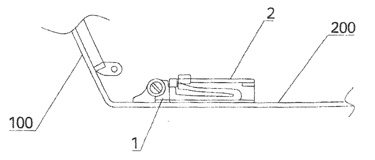
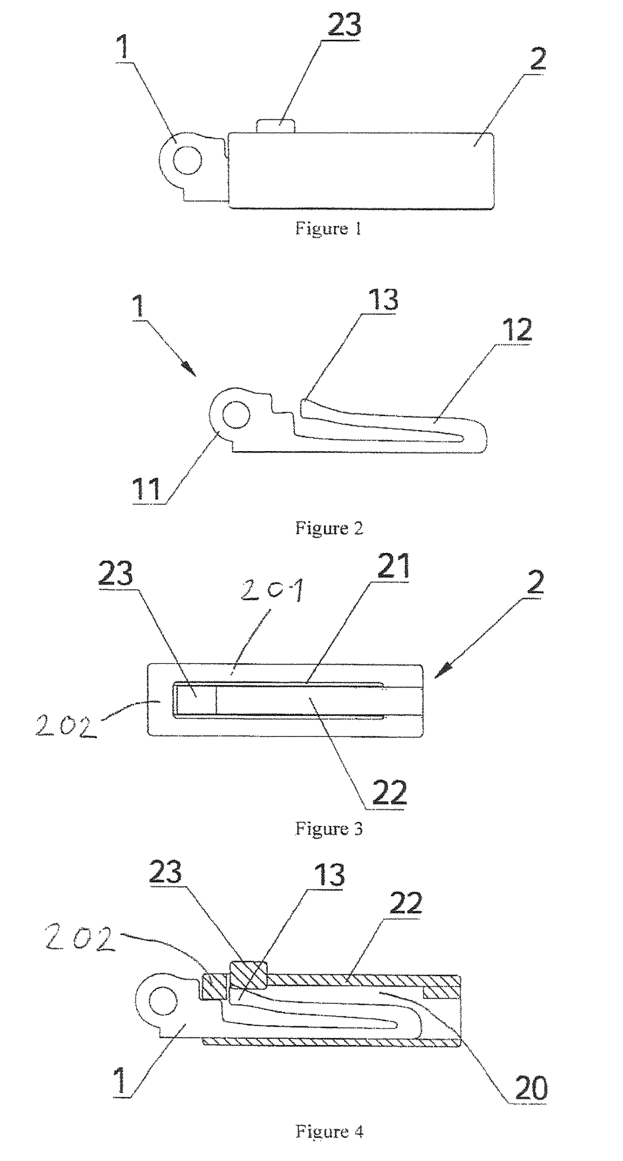
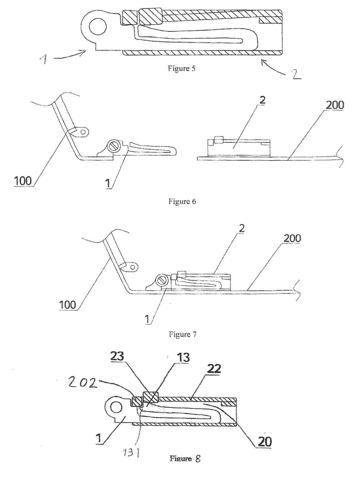
[0032]As shown in FIG. 1, the quick-release connecting assembly comprises a spring core 1 and a socket 2.

[0033]As shown in FIG. 2, said spring core 1 comprises a sleeve-connected elastic portion 12 having a U-shape, and a clamping boss 13 is set on said sleeve-connected elastic portion 12, at the end of one first arm of said U-shaped elastic portion 12. Said spring core 1 further comprises a pivot connection portion 11 connected to the second arm of the U-shaped elastic portion 12. The pivot connection portion 11 is arranged to rotationally connect the spring core 1 to the frame 100, as can be seen on FIGS. 6 and 7. So the pivot connection portion 11 provides a substrate to facilitate the fixing and connection of the external part of spring core to the frame 100, for instance by means of screws.

[0034]The structure of ...


PUM


Abstract

A quick-release connecting assembly, including a spring core and a socket, said spring core including a sleeve-connected elastic portion and a clamping boss set on said sleeve-connected elastic portion; one end of said socket is opened to form a hole adapted to receive the spring core plugged into and a hole wall surrounding said hole. A clamping slot is adapted to receive said clamping boss formed in said hole wall, said slot determining an abutment edge for abutting the clamping boss. A push member is located in correspondence to said clamping boss and is set on the socket at the clamping slot, said sleeve-connected elastic portion being arranged to elastically engage the clamping boss with the abutment edge when the sleeve-connected elastic portion of the spring core is plugged into the hole of the socket.

Description

TECHNICAL FIELD[0001]The present invention relates to spectacles, and more particularly to a connecting assembly used in spectacles to releasably connect the front frame and the temples of such spectacles.BACKGROUND ART[0002]The connecting piece (also known as hinge) used to connect the frame and a temple is an important component in spectacles. The connecting piece in spectacles is generally a hinge screw. The hinge screw can effectively connect a temple and the frame. It is difficult to disassemble or assemble a spectacle where the temple and the frame are connected with a hinge screw because an auxiliary tool such as screwdriver or any other tool is required, however. When the frame or a temple needs to be replaced, the user usually needs to go to a spectacles store to replace it. This brings great inconvenience to the user. On the other hand, as the spectacle industry is developing towards a direction of fashion, consumers set a higher demand for the diversity of spectacle model...

Claims


Application Information

Patent Timeline
Patent Type & Authority Applications(United States)
IPC IPC(8): G02C5/14
CPCG02C5/146G02C2200/04G02C2200/08G02C2200/22Y10T24/45529A44B11/263
Inventor PAN, JINGQING
Owner GRANDVISION GRP HLDG
Why Eureka
Try Eureka