Image forming apparatus, control method, and non-transitory recording medium

a technology of image forming apparatus and control method, which is applied in the direction of electrographic process apparatus, visual presentation, instruments, etc., can solve the problem of not disclosing the timing appropriately

Active Publication Date: 2018-03-01
KONICA MINOLTA INC
View PDF4 Cites 1 Cited by
  • Summary
  • Abstract
  • Description
  • Claims
  • Application Information

AI Technical Summary

Benefits of technology

[0017]Preferably, the control device outputs the enable signal if a predetermined time elapses after the rotation speed of the polygon mirror falls into a determined range, and reduces the predetermined time as the atmosphere pressure increases.

Problems solved by technology

However, the above mentioned patent documents do not disclose how appropriately the timing of outputting the print enable signal is controlled according to the ambient atmospheric pressure.

Method used


Image

  • Image forming apparatus, control method, and non-transitory recording medium
  • Image forming apparatus, control method, and non-transitory recording medium
  • Image forming apparatus, control method, and non-transitory recording medium

Examples


first embodiment

Summary of First Embodiment

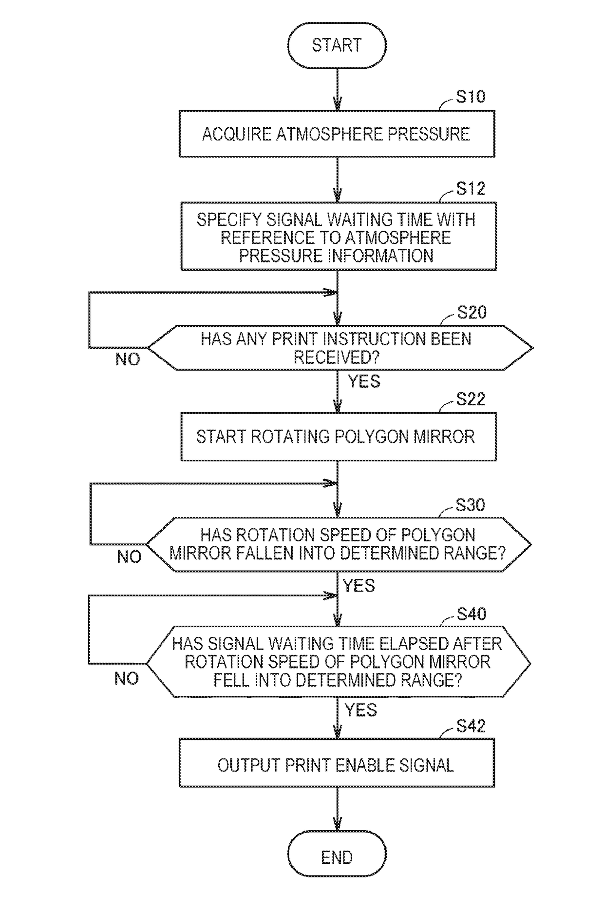
[0136]As the ambient atmospheric pressure increases, rotation of the polygon mirror 313 is stabilized earlier. For this reason, the image forming apparatus 100 according to the first embodiment advances the timing of outputting the print enable signal as the ambient atmospheric pressure increases. As a result, the image forming apparatus 100 can reduce the printing time, and it is possible to reduce the waiting time of the user.

Second Embodiment

[0137][Outline]

[0138]The load which is applied to the polygon mirror 313 during rotation fluctuates according to the internal temperature of the image forming apparatus 100. For this reason, the timing at which rotation of the polygon mirror 313 is stabilized also varies according to the internal temperature of the image forming apparatus 100. In other words, an appropriate timing of outputting the print enable signal varies according to the internal temperature of the image forming apparatus 100.

[0139]The image for...

second embodiment

Summary of Second Embodiment

[0153]Not only as the ambient atmospheric pressure increases but also as the ambient temperature decreases, rotation of the polygon mirror is stabilized earlier. For this reason, the image forming apparatus 100 according to the second embodiment advances the timing of outputting the print enable signal not only as the ambient atmospheric pressure increases but also as the internal temperature of the image forming apparatus 100 decreases. The image forming apparatus 100 determines the timing of outputting the print enable signal on the basis of both of the atmosphere pressure and the temperature, such that it is possible to output the print enable signal at a more appropriate timing. As a result, the image forming apparatus 100 can reduce the printing time, and it is possible to further reduce the waiting time of the user.

[0154]It should be understood that the embodiments disclosed herein are illustrative and non-restrictive in every respect. The scope of ...


PUM


Abstract

An image forming apparatus includes an acquiring unit configured to acquire atmosphere pressure in the installation place of the image forming apparatus, photoconductors, light sources configured to radiate laser light, and a polygon mirror configured to be rotatable. The polygon mirror exposes the photoconductors by reflecting the laser light toward the photoconductors while rotating. The image forming apparatus further includes a control device configured to control rotation of the polygon mirror. The control device outputs an enable signal for allowing the image forming apparatus to perform printing, if rotation of the polygon mirror is stabilized after start of the rotation, and advances the timing of outputting the enable signal as the atmosphere pressure increases.

Description

CROSS-REFERENCE TO RELATED APPLICATIONS[0001]The entire disclosure of Japanese Patent Application No. 2016-168066 filed on Aug. 30, 2016 including description, claims, drawings, and abstract are incorporated herein by reference in its entirety.BACKGROUND OF THE INVENTIONField of the Invention[0002]The present disclosure relates to control of an image forming apparatus, and more particularly, to control of a polygon mirror provided in an image forming apparatus.Description of the Related Art[0003]Image forming apparatuses such as MFP (Multi-Functional Peripheral) are widely known. An electrophotographic image forming apparatus includes, as printing steps, a step of charging a photoconductor, a step of exposing the photoconductor according to the input image pattern, and a step of attaching toner to the electrostatic latent image formed by the exposure step.[0004]The step of exposing the photoconductor will be described below. In the image forming apparatus, a light source emitting la...

Claims


Application Information

Patent Timeline
Patent Type & Authority Applications(United States)
IPC IPC(8): B41J2/385
CPCH04N1/113G03G2215/0404G06K15/1204G03G15/04072G03G15/043G03G15/50G03G21/20G06K15/1219
Inventor EGUCHI, TATSUYAWATANABE, ISAOISHIDA, TAKESHITAKATSU, HIROAKIKIMURA, TAKUNAKASHIMA, ATOMU
Owner KONICA MINOLTA INC
Why Eureka
Try Eureka