
Method for determining a trigger level

a trigger level and level technology, applied in the field of determining the trigger level, can solve the problems of improper method and output jitter, and achieve the effect of reducing output jitter

Inactive Publication Date: 2013-10-17
SIEMENS AG
View PDF12 Cites 0 Cited by
  • Summary
  • Abstract
  • Description
  • Claims
  • Application Information

AI Technical Summary

Benefits of technology

The patent describes a method for reducing output jitter and avoiding false trigger events in a system. The method involves measuring the analog signal and determining the trigger level based on the measured jitter levels. The potential trigger values are evenly spaced to ensure a broad range of different trigger values. The jitter levels are filtered, thresholded, and weighted to ensure proper trigger selection in extreme cases. The method also changes the output only when the input signal is significantly changed to avoid additional phase jitter. The technical effect of the patent is to provide an efficient and reliable method for determining optimal trigger levels and reducing jitter in a system.

Problems solved by technology

Due to natural fluctuations of the analog signal, jitter will occur.
Sometimes this method is not proper, e.g. when additional, lower amplitude peaks can appear in the trigger signal due to reflections.

Method used


Image

  • Method for determining a trigger level
  • Method for determining a trigger level
  • Method for determining a trigger level

Examples


Embodiment Construction

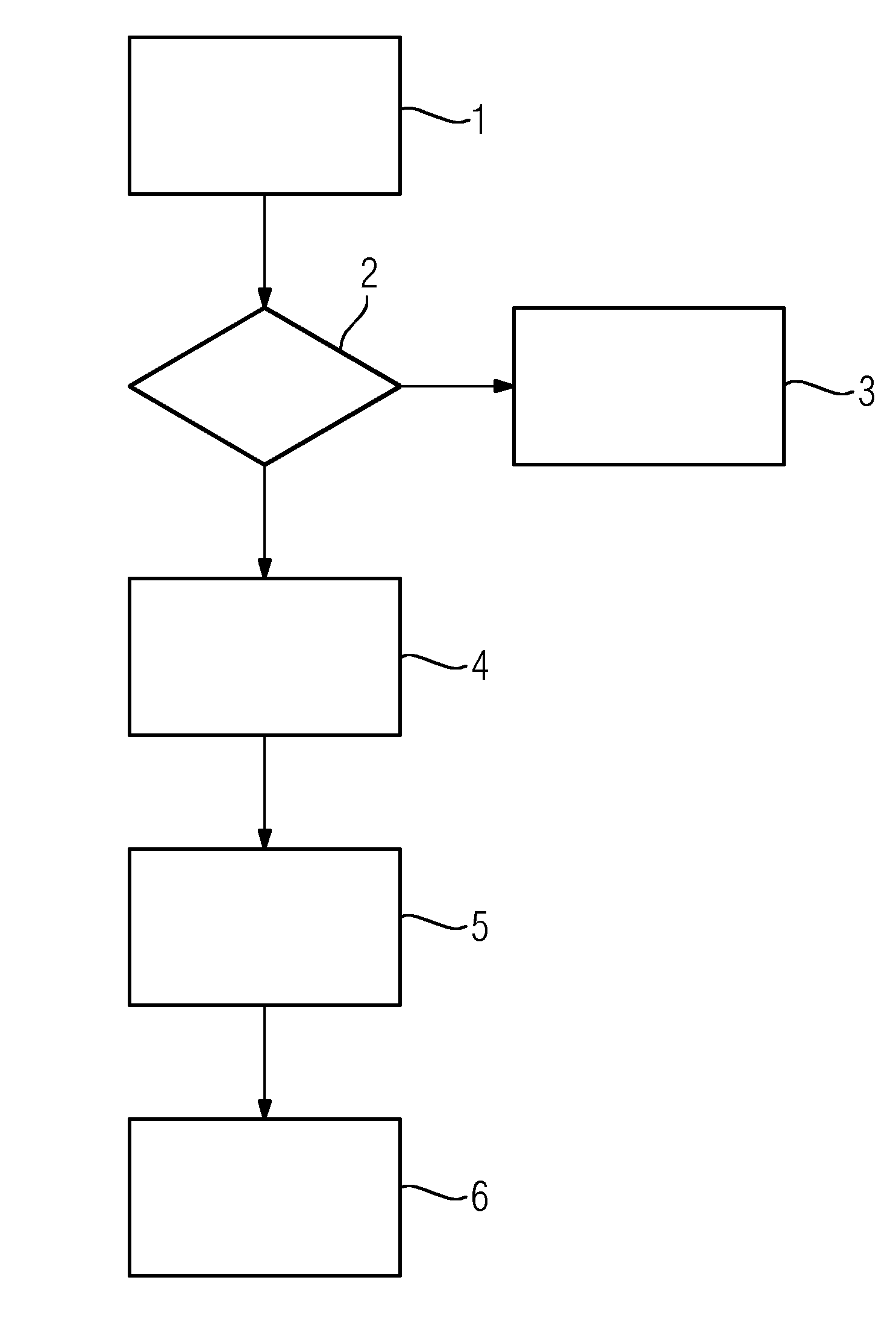
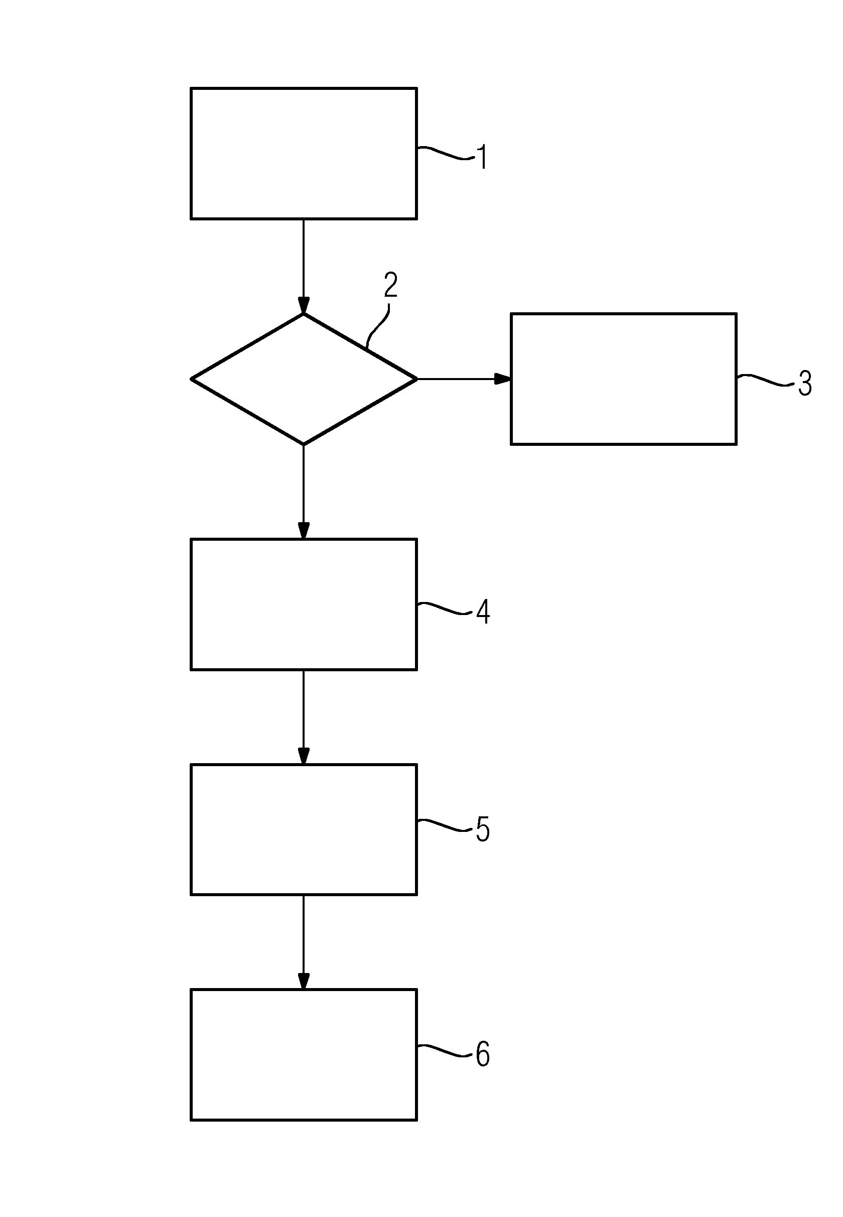
[0024]The method according to the embodiment of the FIGURE requires the following parameters:[0025]Trigger timeout value, T, from which a measurement update time can be calculated[0026]“Low voltage” value[0027]Minimum and maximum “safe area” limits, L1 and L2[0028]Trigger slope direction, bRisingDirection[0029]Number of possible trigger levels to be examined, N

[0030]The timeout value T is a time interval within which the input signal makes at least one period. Safe area limits are limit numbers given in percent. If the interval between the minimum and maximum value of input signal is 0-100%, then minimum and maximum safe area numbers select a smaller interval in which the optimum trigger level can be selected. Trigger slope direction tells, if the trigger level to be determined relates to rising edge (bRisingDirection=TRUE) or falling edge (bRisingDirection=FALSE).

[0031]The method consists of the following states:[0032]STATE1: Measuring 1 the minimum and maximum values of the analog...


PUM


Abstract

A method for determining a trigger level for a periodic analog signal in a digital signal processing system is provided. The method reduces output jitter as much as possible and avoids false trigger events. To this end, the method includes measuring the minimum and maximum values of the signal in a predetermined time, defining a plurality of potential trigger values between the minimum and maximum values, assigning to the respective potential trigger value a jitter value characteristic for the jitter created by processing the signal with the potential trigger value, and determining the optimal trigger level based on the lowest jitter value.

Description

CROSS REFERENCE TO RELATED APPLICATIONS[0001]The present application claims priority to European Patent Office application No. 12163978.5 EP filed Apr. 12, 2012, the entire content of which is hereby incorporated herein by reference.FIELD OF INVENTION[0002]The invention concerns a method for determining a trigger level for a periodic analog signal in a digital signal processing system.BACKGROUND OF INVENTION[0003]Digital signal processing (DSP) is concerned with the representation of discrete time, discrete frequency, or other discrete domain signals by a sequence of numbers or symbols and the processing of these signals. The goal of DSP is usually to measure, filter and / or compress continuous real-world analog signals. The first step is usually to convert the signal from an analog to a digital form, by sampling and then digitizing it using an analog-to-digital converter (ADC), which turns the analog signal into a stream of numbers.[0004]The main applications of DSP are audio signal...

Claims


Application Information

Patent Timeline
IPC IPC(8): H03K3/013
CPCH03K3/013H03K5/082G01R19/16585
Inventor BAKO, TAMASBORGER, THOMASLADANYI, GERGOSZIGETHY, TAMAS
Owner SIEMENS AG
Learn More