Modulated jitter attenuation filter
What is Al technical title?
Al technical title is built by PatSnap Al team. It summarizes the technical point description of the patent document.
a filter and jitter attenuation technology, applied in the field of digital envelope frame communications, can solve the problems of high jitter spikes and require more hardware, and achieve the effect of reducing jitter in mapping information into a sp
Inactive Publication Date: 2008-10-21
MACOM CONNECTIVITY SOLUTIONS LLC
View PDF3 Cites 0 Cited by
Summary
Abstract
Description
Claims
Application Information
AI Technical Summary
This helps you quickly interpret patents by identifying the three key elements:
Problems solved by technology
Method used
Benefits of technology
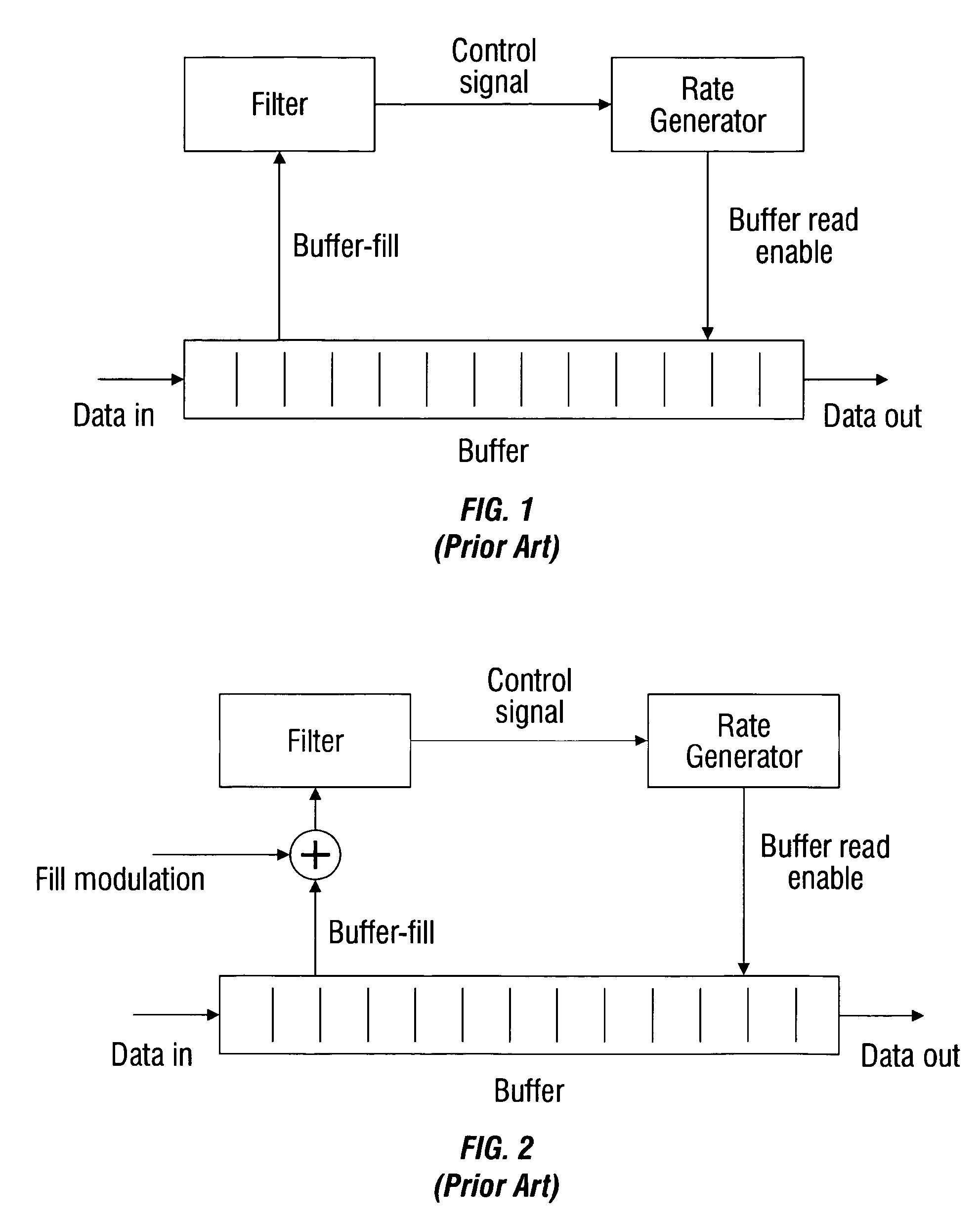
[0037]As noted above, the use of a digital loop filter in a desynchronizer or jitter-attenuator can result in high jitter spikes due to limit cycle behavior. The normal solution is to change the form of the filter, but this solution requires more hardware, which is a disadvantage in high-density applications. The present invention is a hardware-efficient method for controlling the impact of limit cycles and reducing output jitter.
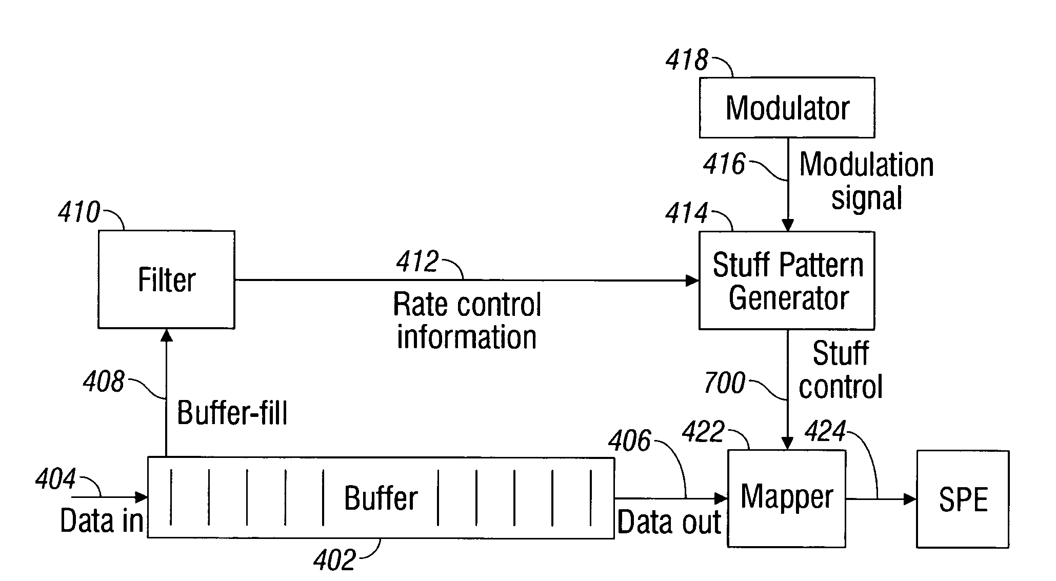
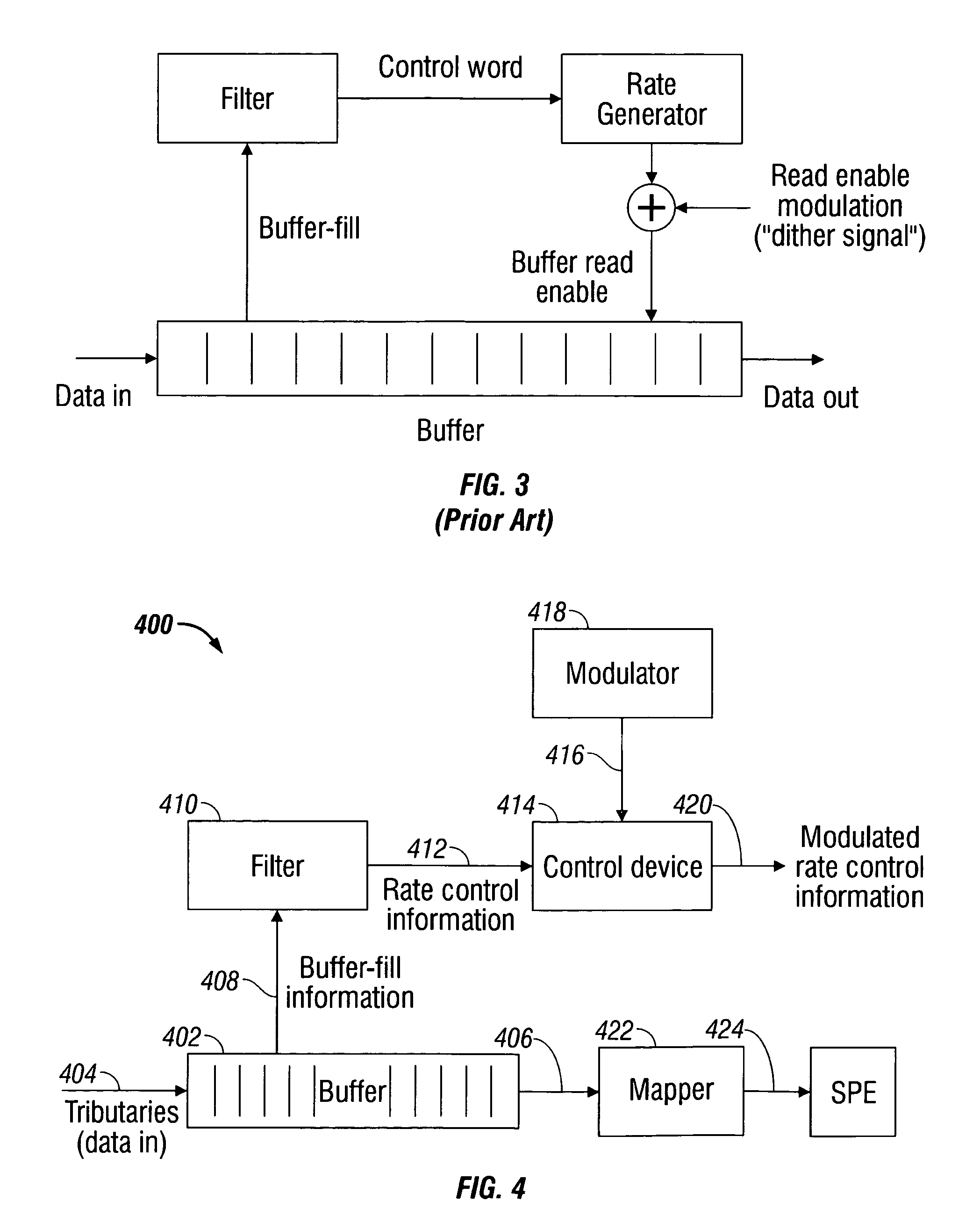
[0038]Accordingly, a modulation method is provided for reducing jitter in the mapping of information into Synchronous Payload Envelopes (SPEs), in a data tributary mapping system. The method comprises buffering data from a plurality of tributaries, and generating buffer-fill information responsive to the buffered data being written and read. The buffer-fill information is filtered, producing rate control information. The rate control information is modulated, and the modulated rate control information is used in controlling the mapping of buffered tributaries into a SPE. The rate control information can be modulated with periodic signals, such as a sine or square wave, or pseudorandom signals with an average value of about zero.
[0041]Additional details of the above-described method and a modulation system for reducing jitter in the mapping information into an SPE are provided below.
Problems solved by technology
As noted above, the use of a digital loop filter in a desynchronizer or jitter-attenuator can result in high jitter spikes due to limit cycle behavior.
The normal solution is to change the form of the filter, but this solution requires more hardware, which is a disadvantage in high-density applications.
Method used
Image
Click on the blue label to locate the original text in one second.
Reading with bidirectional positioning of images and text.
Examples
Embodiment Construction
[0053]Various embodiments are now described with reference to the drawings. In the following description, for purposes of explanation, numerous specific details are set forth in order to provide a thorough understanding of one or more aspects. It may be evident, however, that such embodiment(s) may be practiced without these specific details. In other instances, well-known structures and devices are shown in block diagram form in order to facilitate describing these embodiments.
[0054]As used in this application, the terms “component,”“module,”“system,” and the like are intended to refer to a computer-related entity, either hardware, firmware, a combination of hardware and software, software, or software in execution. For example, a component may be, but is not limited to being, a process running on a processor, a processor, an object, an executable, a thread of execution, a program, and / or a computer. By way of illustration, both an application running on a computing device and the ...
PUM
Abstract
A system and modulation method are provided for reducing jitter in the mapping of information into Synchronous Payload Envelopes (SPEs), in a data tributary mapping system. The method comprises buffering data from a plurality of tributaries, and generating buffer-fill information responsive to the buffered data being written and read. The buffer-fill information is filtered, producing rate control information. The rate control information is modulated, and the modulated rate control information is used in controlling the mapping of buffered tributaries into a SPE. The rate control information can be modulated with periodic signals, such as a sine or square wave, and pseudorandom signals with an average value of about zero.
Description
RELATED APPLICATIONS[0001]This application is a Continuation-in-part of a application entitled, JITTER AND WANDER REDUCTION APPARATUS, invented by Subrahmanyan et al., Ser. No. 10 / 346,550, filed Jan. 17, 2003, now U.S. Pat. No. 7,212,599 which is incorporated herein by reference.[0002]This application is a Continuation-in-part of a application entitled, SAMPLED ACCUMULATION SYSTEM AND METHOD FOR JITTER ATTENUATION, invented by Subrahmanyan et al, Ser. No. 11 / 525,656, filed on Sep. 22, 2006, which is incorporated herein by reference.[0003]This application is a Continuation-in-part of a application entitled, TIMESHARED JITTER ATTENUATOR IN MULTI-CHANNEL MAPPING APPLICATIONS, invented by Spires et al, Ser. No. 11 / 541,176, filed on Sep. 29, 2006, which is incorporated herein by reference.BACKGROUND OF THE INVENTION[0004]1. Field of the Invention[0005]This invention generally relates to digital envelope-framed communications and, more particularly, to a system and method for filtering bu...
Claims
Application Information
Patent Timeline
Application Date:The date an application was filed.
Publication Date:The date a patent or application was officially published.
First Publication Date:The earliest publication date of a patent with the same application number.
Issue Date:Publication date of the patent grant document.
PCT Entry Date:The Entry date of PCT National Phase.
Estimated Expiry Date:The statutory expiry date of a patent right according to the Patent Law, and it is the longest term of protection that the patent right can achieve without the termination of the patent right due to other reasons(Term extension factor has been taken into account ).
Invalid Date:Actual expiry date is based on effective date or publication date of legal transaction data of invalid patent.