Stimulation devices and methods

a technology of stimulation device and ocular surface, which is applied in the field of stimulation system, can solve the problems of dramatic shift in quality of life, debilitating disease that affects millions of patients worldwide, and can cripple some patients, and achieve the effect of increasing tear production

Active Publication Date: 2018-03-08
THE BOARD OF TRUSTEES OF THE LELAND STANFORD JUNIOR UNIV +1
View PDF4 Cites 20 Cited by
  • Summary
  • Abstract
  • Description
  • Claims
  • Application Information

AI Technical Summary

Benefits of technology

The patent describes a device and method for stimulating tissues in the eye, specifically the lacrimal gland, using a microstimulator. The microstimulator is a small, flexible device that can be implanted near the lacrimal gland and powered by a battery. The device contains a passive stimulation circuit with safety features such as current limiting and zener diodes. The device can be controlled using a microcontroller and can generate a ramped stimulation signal. The microstimulator can be injected into the eye through a needle and can be positioned near the lacrimal gland or within the eye. The stimulation can selectively target specific nerves without causing movement of the eye or other parts of the eye. The device can conform to the shape of the lacrimal gland after implantation. The technical effects of this patent include improved methods for stimulating the lacrimal gland with a microstimulator and enhanced safety features.

Problems solved by technology

Dry eye syndrome is a debilitating disease that affects millions of patients worldwide and can cripple some patients.
This disease often inflicts severe ocular discomfort, results in a dramatic shift in quality of life, induces poor ocular surface health, substantially reduces visual acuity and can threaten vision.
Patients with severe dry eye develop a sensitivity to light and wind that prevents substantial time spent outdoors, and they often cannot read or drive because of the discomfort.
Current treatment options provide little relief for those suffering from severe conditions.
None of these treatments provides sufficient relief or treatment of the disease.

Method used


Image

  • Stimulation devices and methods
  • Stimulation devices and methods
  • Stimulation devices and methods

Examples


Embodiment Construction

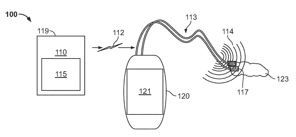
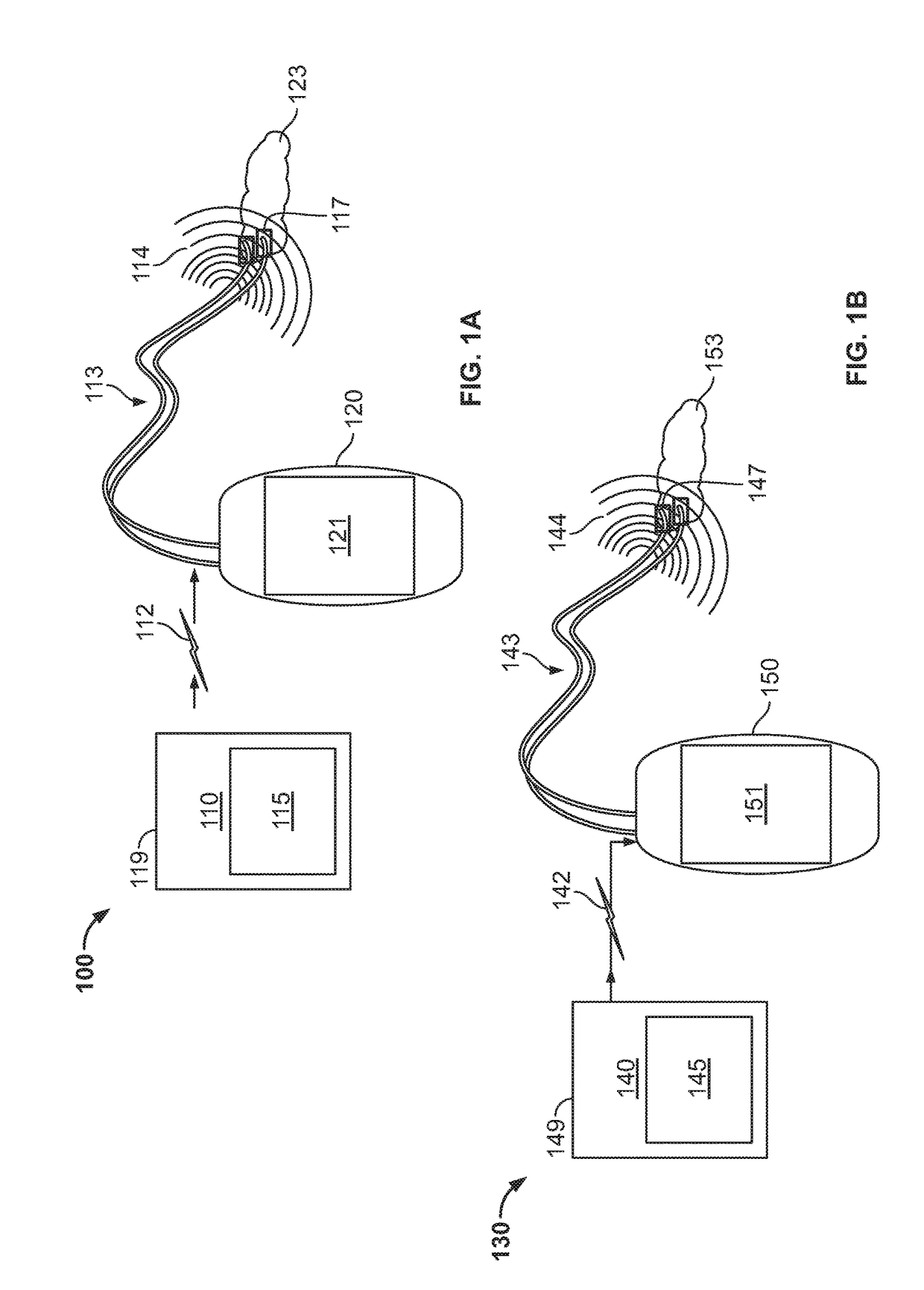
[0061]Described here are stimulation systems for stimulating anatomical targets in a patient for the treatment of one or more conditions. The stimulation systems may include at least one controller and at least one microstimulator. The controller may be implemented as a part of the microstimulator, or as a separate device. When formed as a separate device, the controller may communicate with the microstimulator via a wireless and / or wired connection. The controller may produce a waveform signal which may convey power and / or information to the microstimulator and the microstimulator may deliver one or more stimulation signals to an anatomical target based on the waveform signal.

[0062]The stimulation systems may be used to stimulate any suitable anatomical target or targets to treat a number of conditions. In some variations, the stimulation systems described here may be used to treat dry eye. For example, the stimulation systems may be used to stimulate one or more nerves, tissues, g...


PUM


Abstract

Described here are stimulation systems and methods for stimulating one or more anatomical targets in a patient for treatment conditions such as dry eye. The stimulation system may include a controller and a microstimulator. The components of the controller and microstimulator may be implemented in a single unit or in separate devices. When implemented separately, the controller and microstimulator may communicate wirelessly or via a wired connection. The microstimulator may generate pulses from a signal received from the controller and apply the signal via one or more electrodes to an anatomical target. In some variations, the microstimulator may include a passive generation circuit configured to generate a pulse based on a signal received from the controller.

Description

CROSS-REFERENCE TO RELATED APPLICATIONS[0001]This application is a continuation of U.S. application Ser. No. 13 / 441,806, filed on Apr. 6, 2012, which is a continuation-in-part of U.S. application Ser. No. 13 / 298,042, filed on Nov. 16, 2011, issued as U.S. Pat. No. 8,918,181 on Dec. 23, 2014, which claims priority to U.S. Provisional Application Ser. No. 61 / 414,293, filed on Nov. 16, 2010, to U.S. Provisional Application Ser. No. 61 / 433,645, filed Jan. 18, 2011, to U.S. Provisional Application Ser. No. 61 / 433,649, filed Jan. 18, 2011, and to U.S. Provisional Application Ser. No. 61 / 433,652, filed on Jan. 18, 2011. U.S. application Ser. No. 13 / 441,806 also claims priority to U.S. Provisional Application Ser. No. 61 / 473,141, filed on Apr. 7, 2011, and to U.S. Provisional Application Ser. No. 61 / 523,732, filed on Aug. 15, 2011. Each of the foregoing applications is hereby incorporated by reference in its entirety.FIELD[0002]The present invention relates generally to stimulation systems ...

Claims


Application Information

Patent Timeline
Patent Type & Authority Applications(United States)
IPC IPC(8): A61N1/36A61N1/372A61N1/375
CPCA61N1/3756A61N1/37211A61N1/36046A61N1/3606A61N1/36057A61N1/37205
Inventor ACKERMANN, DOUGLAS MICHAELLOUDIN, JAMES DONALDKUZMA, JANUSZPALANKER, DANIELWETENKAMP, SCOTT FRANKLIN
Owner THE BOARD OF TRUSTEES OF THE LELAND STANFORD JUNIOR UNIV
Why Eureka
Try Eureka