Virtual angle-of-arrival/angle-of-departure tracking

Active Publication Date: 2018-03-15
AVAGO TECH INT SALES PTE LTD
View PDF2 Cites 13 Cited by
  • Summary
  • Abstract
  • Description
  • Claims
  • Application Information

AI Technical Summary

Problems solved by technology

However, these techniques require knowledge of relative spatial positioning of the devices so that th

Method used


Image

  • Virtual angle-of-arrival/angle-of-departure tracking
  • Virtual angle-of-arrival/angle-of-departure tracking
  • Virtual angle-of-arrival/angle-of-departure tracking

Examples


Embodiment Construction

[0013]For purposes of reading the description of the various embodiments below, the following descriptions of the sections of the specification and their respective contents may be helpful:[0014]Section A describes embodiments of systems and methods for virtual angle-of-arrival and angle-of-departure tracking; and[0015]Section B describes a network environment and computing environment which may be useful for practicing embodiments described herein.

A. Virtual Angle-of-Arrival and Angle-of-Departure Tracking

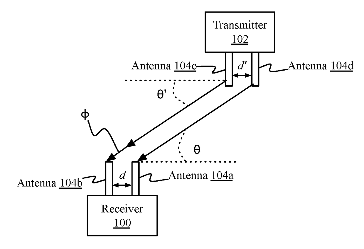
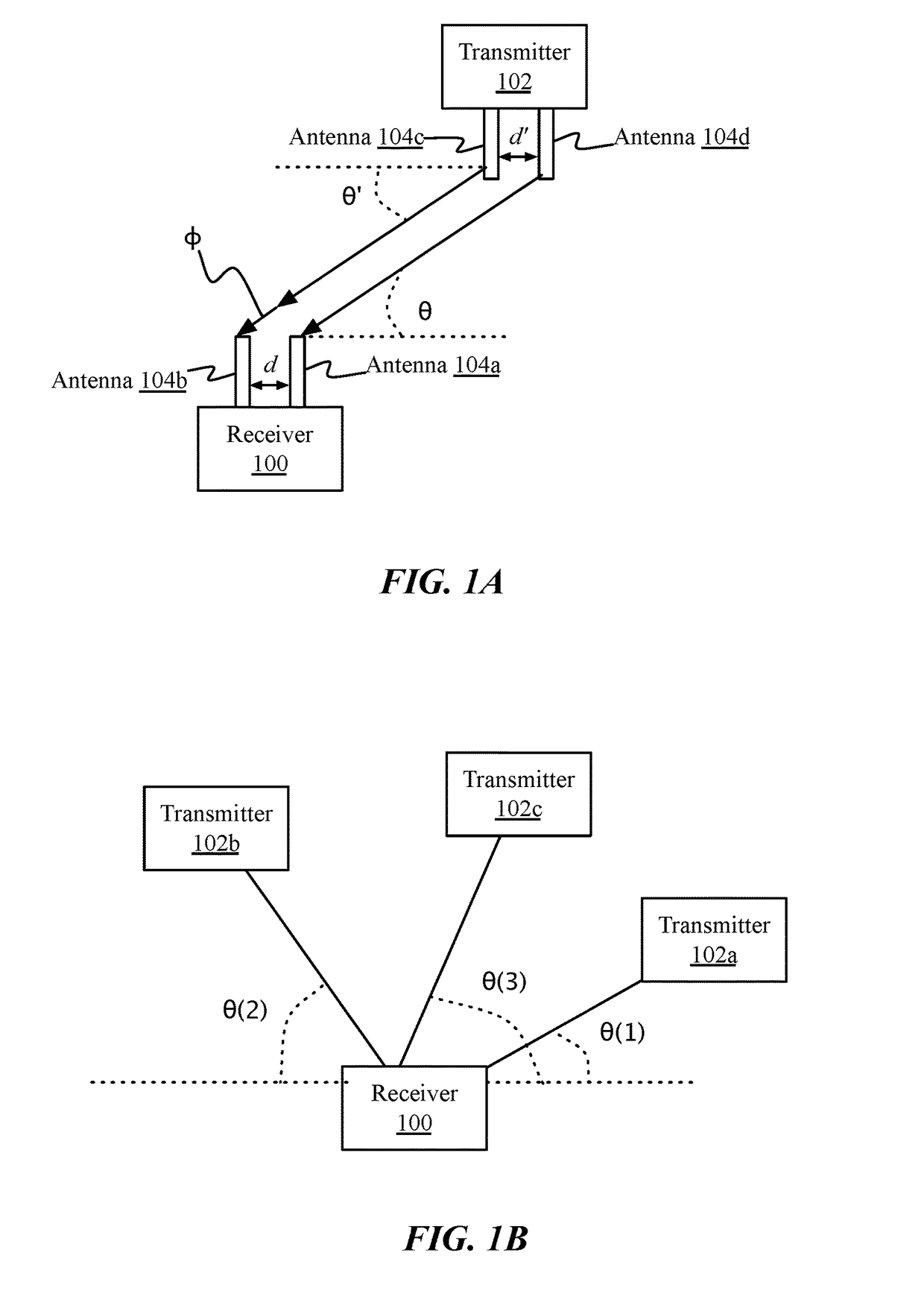
[0016]Wireless devices, such as Bluetooth Low Energy (BLE) devices, can deploy antenna arrays with known spatial and element characteristics (e.g. distance between elements, frequency tuning, etc.) for the purposes of obtaining relative angular positioning of a transmitting device by a receiving device. For example, referring briefly to FIG. 1A, illustrated is a simplified diagram of a multi-antenna receiver 100 and a transmitter 102, not drawn to scale. Receiver 100 may have two ...


PUM


Abstract

In some aspects, the disclosure is directed to methods and systems for virtual angle-of-arrival (AoA) or angle-of-departure (AoD) tracking for virtually tracking multiple Targets. The wireless devices (e.g. Tracker and Targets) may participate in a mesh configuration and share data within the mesh. A first device may purport to be a virtual tracker, while acting as an AoA or Angle of Departure (AoD) Target. The devices being tracked (e.g. virtual targets), may instead operate as Trackers. Processor- and energy-intensive calculations may be distributed to the virtual targets and transmitted via the mesh for aggregation at the virtual tracker.

Description

RELATED APPLICATIONS[0001]The present application claims the benefit of and priority to U.S. Provisional Application No. 62 / 395,104, entitled “Virtual Angle-of-Arrival / Angle-of-Departure Tracking,” filed Sep. 15, 2016, the entirety of which is hereby incorporated by reference.FIELD OF THE DISCLOSURE[0002]This disclosure generally relates to systems and methods for device triangulation wireless communication via antenna arrays.BACKGROUND OF THE DISCLOSURE[0003]Wirelessly communicating devices may utilize a plurality of antennas, deployed in an array, for beamforming and directional communication with other devices, increasing signal-to-noise ratios, bandwidth, and overall efficiency, as well as for determining relative positioning or tracking of a wireless device within a two or three-dimensional space. However, these techniques require knowledge of relative spatial positioning of the devices so that the transmitting and receiving arrays may be properly tuned, and accordingly have hi...

Claims


Application Information

Patent Timeline
IPC IPC(8): G01S13/68G01S13/42
CPCG01S13/68G01S13/42G01S13/74G01S3/28G01S5/00
Inventor POLO, ANGELHERNDON, MIKE DAVIDBAKER, TOM F.
Owner AVAGO TECH INT SALES PTE LTD
Why Eureka
Try Eureka