Unmanned aerial vehicle system and method with environmental sensing

a technology of environmental sensing and unmanned aerial vehicles, applied in the field of aerial vehicles, can solve the problems of both ambient environment data capture and vision-based remote user drone control, which can become problematic in low-light conditions

Active Publication Date: 2018-03-15
HANGZHOU ZERO ZERO TECH CO LTD
View PDF3 Cites 28 Cited by
  • Summary
  • Abstract
  • Description
  • Claims
  • Application Information

AI Technical Summary

Benefits of technology

[0004]In one aspect of the present invention, an aerial system is provided. The aerial system includes a body, a lift mechanism, a processing system, a camera, and a sensor module. The lift mechanism is coupled to the body and configured to controllably provide lift and/or thrust. The processing system is configured to control the lift mechanism to provide flight to the aerial system. The camera is coupled to the body and is configured to obtain images of an environment proximate the aerial system. The sensor module is coupled to the body and includes an emitter and a receiver. The receiver is configured to sense data related to an ambient environment associated with the aerial system. The processing system controls a controllable parameter of the lift mechanism or the emitter as a function of the sensed data.
[0005]In another aspect of the present invention, a method for operating an aerial system

Problems solved by technology

However, both ambient environment data capture and vision-based remo

Method used


Image

  • Unmanned aerial vehicle system and method with environmental sensing
  • Unmanned aerial vehicle system and method with environmental sensing
  • Unmanned aerial vehicle system and method with environmental sensing

Examples


Embodiment Construction

[0017]The following description of the preferred embodiments of the invention is not intended to limit the invention to these preferred embodiments, but rather to enable any person skilled in the art to make and use this invention.

1. Overview

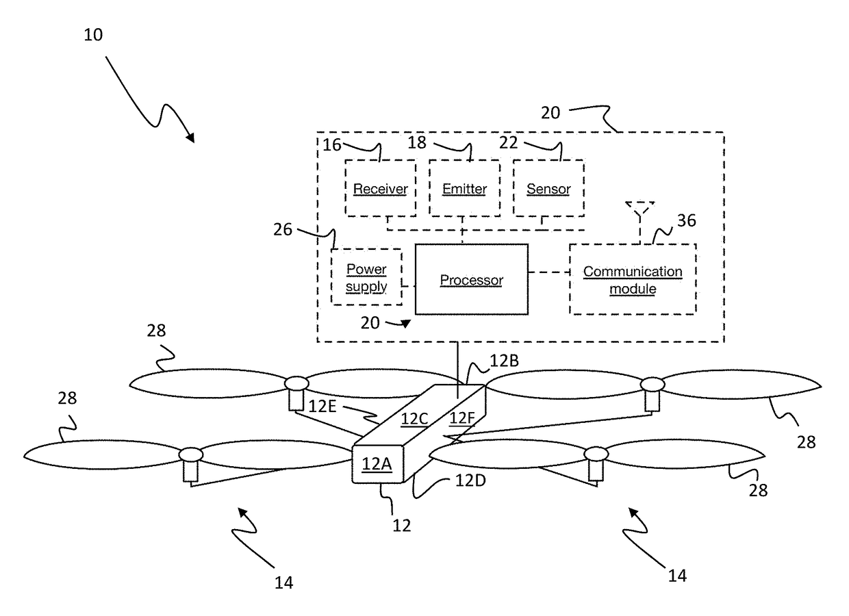
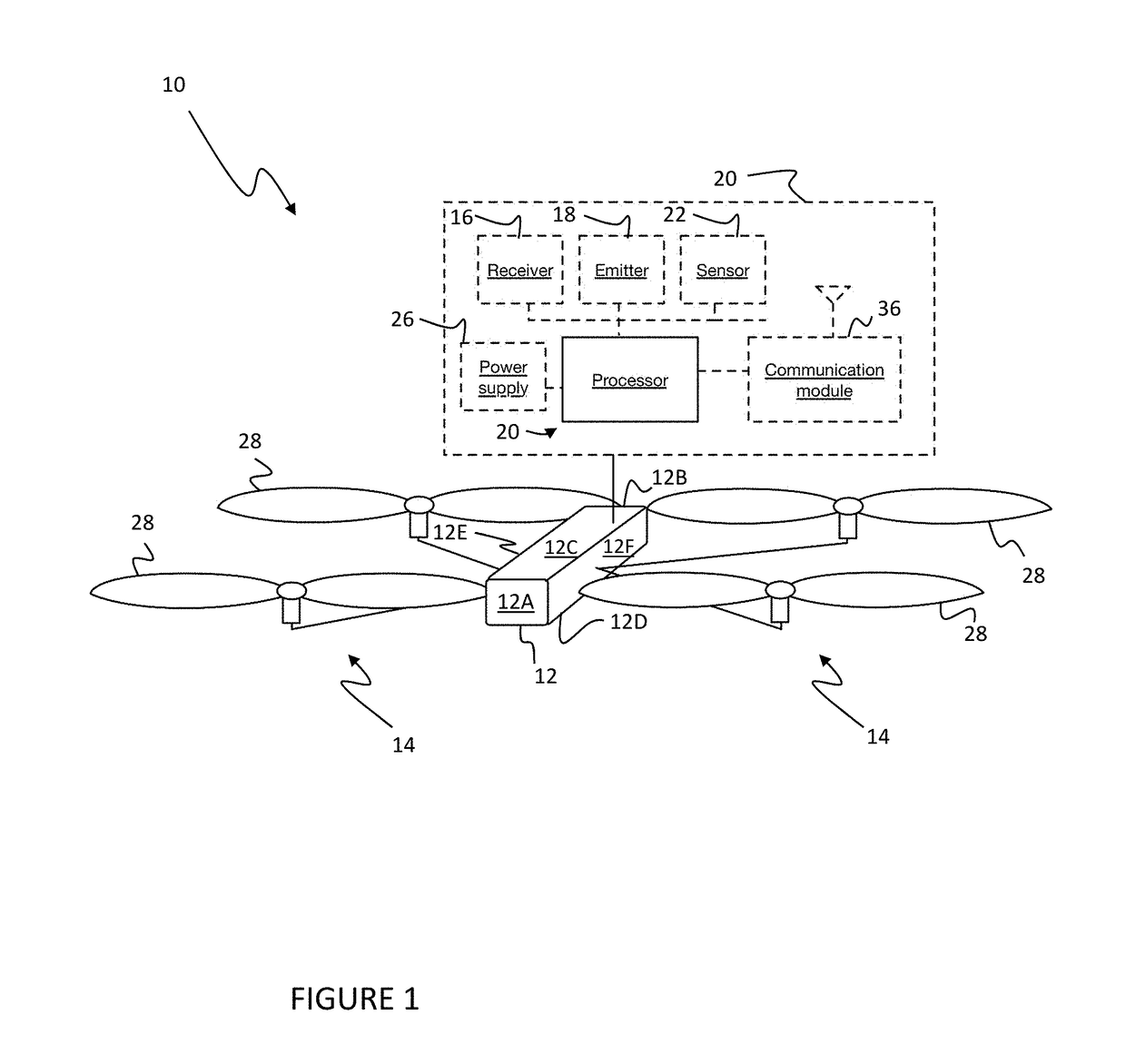
[0018]As shown in FIG. 1, in one embodiment the aerial system 10 (UAV system) includes a housing or body 12, a lift mechanism 14, a receiver 16, an emitter, and a processing system 20 including processor. The aerial system 10 may optionally include a set of auxiliary sensors 22, a communication module 24, and a power supply 26. The aerial system 10 functions to automatically adjust emitter signal emission.

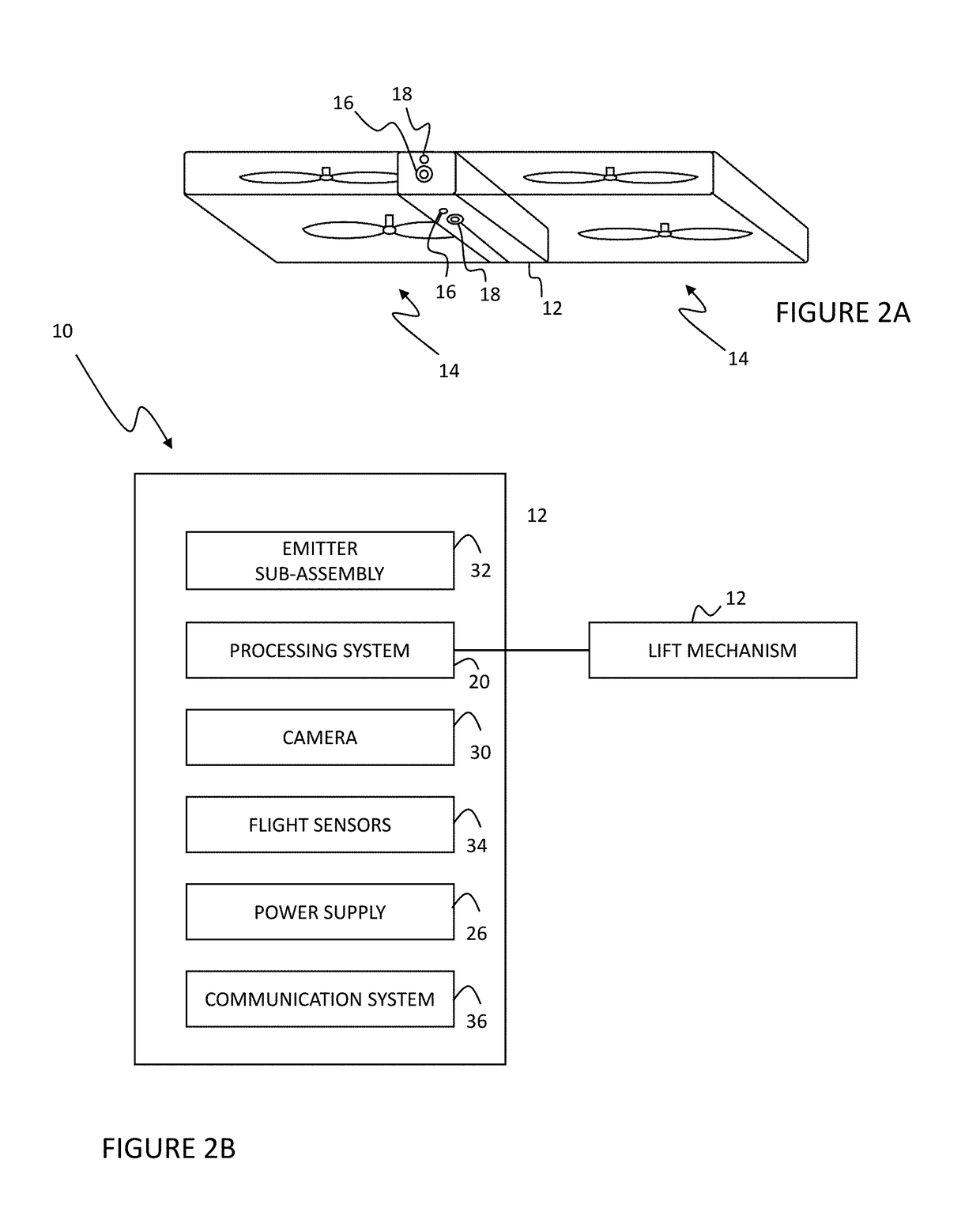
[0019]In a specific variation as shown in FIG. 2, the aerial system 10 includes a housing 12 with a front 12A, back 12B, top 12C, bottom 12D, and left and right sides 12E, 12F; a set of rotors 28 mounted to the left and right sides; a camera 30 mounted to the housing front, a light-emitting sub-assembly 32 mounted to the front 12A of the housin...


PUM


Abstract

An aerial system and method of operating an aerial system is provided. The aerial system includes a body, a lift mechanism, a processing system, a camera, and a sensor module. The lift mechanism is coupled to the body and configured to controllably provide lift and/or thrust. The processing system is configured to control the lift mechanism to provide flight to the aerial system. The camera is coupled to the body and is configured to obtain images of an environment proximate the aerial system. The sensor module is coupled to the body and includes an emitter and a receiver. The receiver is configured to sense data related to an ambient environment associated with the aerial system. The processing system controls a controllable parameter of the lift mechanism or the emitter as a function of the sensed data.

Description

CROSS-REFERENCE TO RELATED APPLICATION[0001]This application claims benefit of U.S. Provisional Patent Application Ser. No. 62 / 393,771, filed Sep. 13, 2016, the disclosure of which is hereby incorporated by referenced in its entirety.TECHNICAL FIELD[0002]This invention relates generally to the aerial vehicle field, and more specifically to a new and useful system and method for environmental sensing in the aerial vehicle field.BACKGROUND OF THE INVENTION[0003]Unmanned aerial vehicles (UAVs, or drones) are oftentimes used to record data about the ambient environment. For example, drones can be used to record images or video of the ambient environment during flight. These conventional UAVs (e.g., consumer drones) are typically remotely operated by a user using vision-based methods, wherein the user either uses line of sight to the drone to control flight and / or avoid obstacles, or uses the video feed from the drone to control flight and / or avoid obstacles. However, both ambient enviro...

Claims


Application Information

Patent Timeline
IPC IPC(8): G05D1/10G05D1/00B64D47/08B64C39/02H04N7/18H04N5/225G01S13/93G01S13/935G01S15/86G01S15/93G01S17/86G01S17/89G01S17/933
CPCG05D1/102G05D1/0094B64D47/08B64C39/024H04N7/185H04N5/2256G01S13/08G01S15/08G01S17/08B64C2201/127B64C2201/141B64C2201/108B64C2201/027G01S15/93G01S13/867G01S13/882G01S13/93G01S17/89B64D45/04B64D47/02G05D1/0038G01S13/935G01S15/86Y02T50/50H04N23/56H04N23/51B64U10/13B64U2101/30B64U30/20B64U2201/10G01S17/933G01S17/86G01S13/86
Inventor QIN, YUSENZHANG, TONGWANG, MENQIU
Owner HANGZHOU ZERO ZERO TECH CO LTD
Why Eureka
Try Eureka