
Optical element and display device

Active Publication Date: 2018-03-22
SEIKO EPSON CORP
View PDF2 Cites 3 Cited by
  • Summary
  • Abstract
  • Description
  • Claims
  • Application Information

AI Technical Summary

Benefits of technology

The technical effect of this patent is to provide a display device that reduces stripy unevenness and double viewing of external images using an optical element with partially reflecting mirrors that have different reflectances for different polarized light components. This optical element optimizes the use of light and reduces the intensity difference between reflected lights, resulting in a more uniform display.

Problems solved by technology

The image display devices have problems that striped unevenness is viewed on a display image due to a plurality of partially-transmitting film patterns or stripe patterns of the multiple mirrors, a phenomenon (ghost) in which an external image is dually viewed occurs, and the like.

Method used


Image

  • Optical element and display device
  • Optical element and display device
  • Optical element and display device

Examples


Embodiment Construction

[0032]Hereinafter, an embodiment will be described with reference to the drawings.

[0033]A display device according to the present embodiment is used as, for example, a head-mounted display used by being worn on the head of an observer.

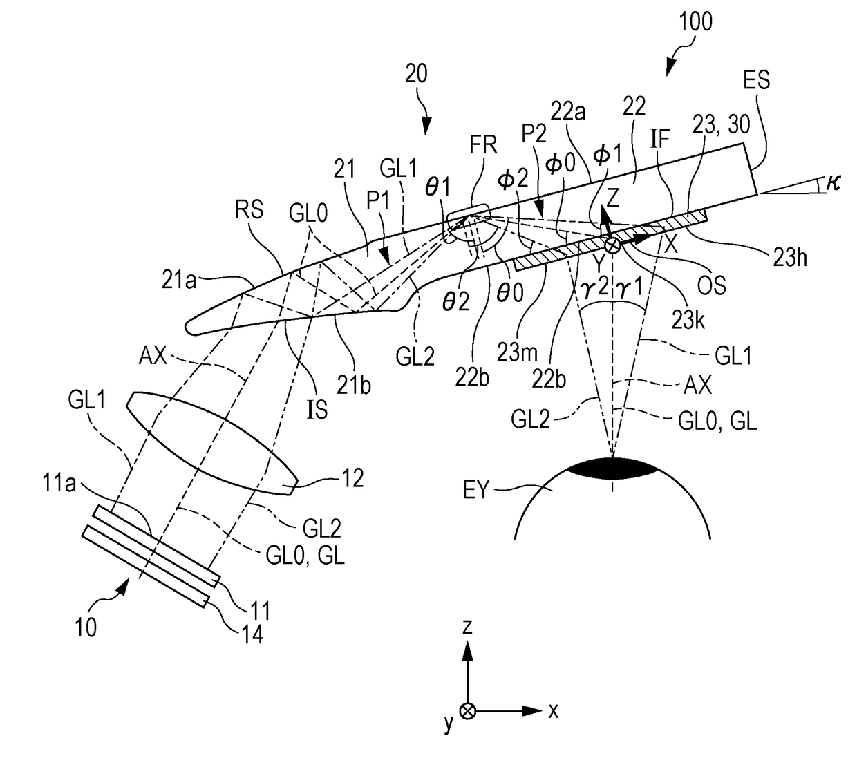
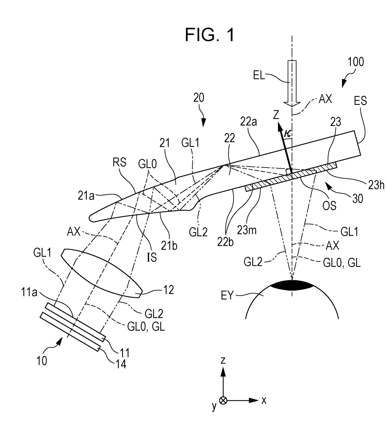
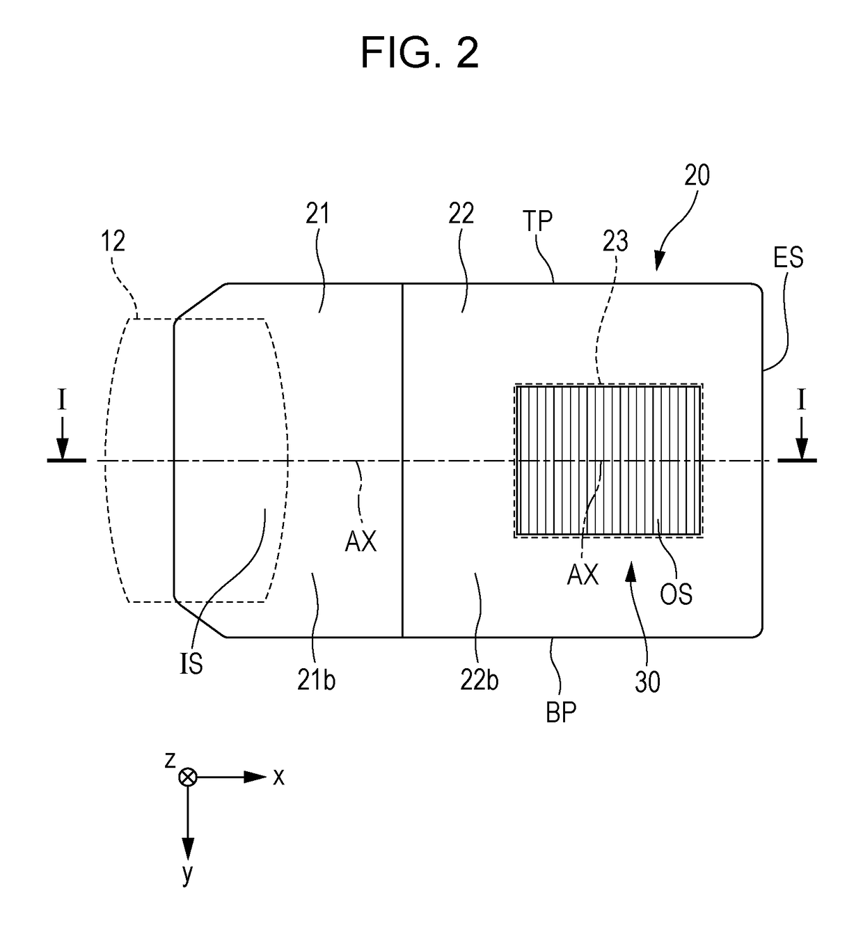
[0034]FIG. 1 is a plan view of the display device according to the embodiment. FIG. 2 is a rear view of a light guiding device viewed from an observer side. FIG. 3 is a view illustrating a light path of image light in the light guiding device.

[0035]In the following drawings, scales of dimensions may be changed by configuration elements so as to make each configuration element be easily viewed.

Overall Configuration of Light Guiding Device and Display Device

[0036]As illustrated in FIG. 1, the display device 100 includes an image forming device 10 and a light guiding device 20. FIG. 1 corresponds to a cross section I-I of the light guiding device 20 illustrated in FIG. 2.

[0037]The display device 100 allows the observer to view an image formed by the image...


PUM


Abstract

An optical element includes partially reflecting mirrors provided in parallel to each other with an interval therebetween, reflect a part of image light and external light, and transmit another part of the image light and the external light; and a transmitting member interposed between adjacent two partially reflecting mirrors of the partially reflecting mirrors. The light-transmissive member includes an incidence surface on which the image light and the external light are incident and an exit surface from which the image light and the external light are exited. Each of the partially reflecting mirrors is disposed to be inclined with respect to the incidence surface and the exit surface. The partially reflecting mirrors include at least one first partially reflecting mirror and at least one second partially reflecting mirror having different reflectances with respect to predetermined polarized light components included in the image light and the external light.

Description

BACKGROUND1. Technical Field[0001]The present disclosure relates to an optical element and a display device.2. Related Art[0002]Recently, an image display device such as a head-mounted display, which is used by being worn on the head of an observer, is provided as one of wearable information devices. There is also known an image display device capable of simultaneously and visually recognizing both an image generated by a display element and an external image when the observer wears the image display device, that is, a so-called see-through type image display device.[0003]JP-A-2012-008356 describes an image display device that includes a light source and scanning means including a first mirror, first light deflection means, a second mirror, and second light deflection means, and that guides light exited from the second light deflection means to the eye of the observer. JP-A-2012-008356 describes that each of a plurality of partially-transmitting films configuring the second light de...

Claims


Application Information

Patent Timeline
IPC IPC(8): G02B27/01G02B27/14G02B27/28
CPCG02B27/0172G02B27/145G02B27/283G02B2027/0125G02B2027/011G02B6/00G02B2027/012
Inventor YOSHIDA, SHOHEIMATSUKI, HAYATO
Owner SEIKO EPSON CORP
Learn More