Method and apparatus for determining position of routing node and terminal equipment

a terminal equipment and routing node technology, applied in the field of communication technologies, can solve the problems of large effect on network performance and cost, and cannot ensure network deployment reliability, and achieve the effect of ensuring data transmission performance of the network

Active Publication Date: 2018-03-29
FUJITSU LTD
View PDF1 Cites 3 Cited by
  • Summary
  • Abstract
  • Description
  • Claims
  • Application Information

AI Technical Summary

Benefits of technology

[0021]An advantage of the embodiments of this disclosure exists in that with the embodiments of this disclosure, in determining a position of a routing node, optimizing the number of routing nodes and optimizing routing paths are both taken into account, thereby obtaining a routing node deployment scheme with minimum routing nodes and which can also ensure data transmission performance of the network.

Problems solved by technology

And the number of the routing nodes in the network usually occupies a very large proportion, that is, a hardware cost, a deployment cost and a maintenance cost of positions of the routing nodes are important components of a network cost.
Hence, selection of positions of routing nodes has a large effect on performance and cost of a network.
However, the above methods cannot ensure reliability of network deployment and achieve an optimal deployment effect.

Method used


Image

  • Method and apparatus for determining position of routing node and terminal equipment
  • Method and apparatus for determining position of routing node and terminal equipment
  • Method and apparatus for determining position of routing node and terminal equipment

Examples


embodiment 1

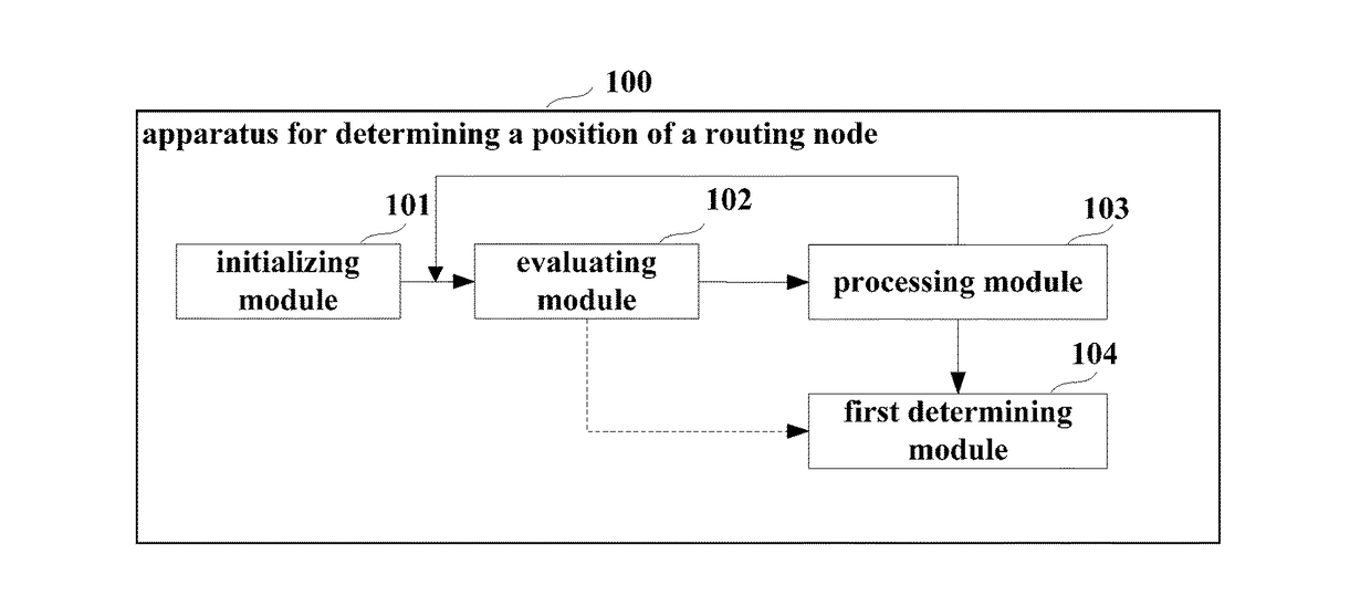
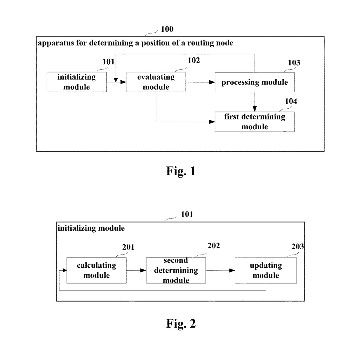
[0045]The embodiment of this disclosure provides an apparatus for determining a position of a routing node. FIG. 1 is a schematic diagram of the apparatus. Referring to FIG. 1, the apparatus 100 includes an initializing module 101, an evaluating module 102, a processing module 103 and a first determining module 104. In this embodiment, the initializing module 101 generates a 0-th generation routing node deployment scheme set according to a link connection relationship among sensor nodes, a gateway node and deployable routing nodes in a network, the evaluating module 102 calculates a fitness of each routing node deployment scheme in a j-th generation routing node deployment scheme set, the fitness being a function of a relationship between a minimum cost path and the number of routing nodes of each routing node deployment scheme, and j being an integer greater than or equal to 0, the processing module 103 processes the j-th generation routing node deployment scheme set according to t...

embodiment 2

[0112]The embodiment of this disclosure provides terminal equipment, including the apparatus for determining a position of a routing node described in Embodiment 1.

[0113]FIG. 13 is a schematic diagram of the terminal equipment. As shown in FIG. 13, the terminal equipment 1300 includes the apparatus 100 for determining a position of a routing node, the apparatus 100 being configured to: generate a 0-th generation routing node deployment scheme set according to a link connection relationship among sensor nodes, a gateway node and deployable routing nodes in a network; calculate a fitness of each routing node deployment scheme in a j-th generation routing node deployment scheme set, the fitness being a function of a relationship between a minimum cost path and the number of routing nodes of each routing node deployment scheme, and j being an integer greater than or equal to 0; process the j-th generation routing node deployment scheme set according to the fitness, so as to generate a (...

embodiment 3

[0121]The embodiment of this disclosure provides a method for determining a position of a routing node. As principles of the method for solving problems are similar to that of the apparatus in Embodiment 1, the implementation of the apparatus in Embodiment 1 may be referred to for implementation of the method, with identical contents being not going to be described herein any further.

[0122]FIG. 15 is a flowchart of an implementation of the method for determining a position of a routing node of this embodiment. Referring to FIG. 15, the method includes:

[0123]step 1501: a 0-th generation routing node deployment scheme set is generated according to a link connection relationship among sensor nodes, a gateway node and deployable routing nodes in a network;

[0124]step 1502: a fitness of each routing node deployment scheme in a j-th generation routing node deployment scheme set is calculated, the fitness being a function of a relationship between a minimum cost path and the number of routi...


PUM


Abstract

A method and apparatus for determining a position of a routing node and terminal equipment. Where the method includes: generating a 0-th generation routing node deployment scheme set according to a link connection relationship among sensor nodes, a gateway node and deployable routing nodes in a network; calculating a fitness of each routing node deployment scheme in a j-th generation routing node deployment scheme set; processing the j-th generation routing node deployment scheme set according to the fitness; and selecting a routing node deployment scheme from the routing node deployment scheme set satisfying the predetermined condition. In determining a position of a routing node, optimizing the number of routing nodes and optimizing routing paths are both taken into account, thereby obtaining a routing node deployment scheme with minimum routing nodes and which can also ensure data transmission performance of the network.

Description

CROSS-REFERENCE TO RELATED APPLICATIONS[0001]This application claims the benefit of Chinese Application No. 201610851254.3, filed Sep. 26, 2016, in the Chinese Intellectual Property Office, the disclosure of which is incorporated herein by reference.BACKGROUND1. Field[0002]This disclosure relates to the field of communication technologies, and in particular to a method and apparatus for determining a position of a routing node and terminal equipment.2. Description of the Related Art[0003]As progress of communication technologies continues, wireless sensor networks have developed rapidly, not only bringing convenience to people's lives, but also changing styles of people's production, productivity and lives.[0004]A wireless sensor network includes sensor nodes, routing nodes and a gateway node. In the wireless sensor network, the routing nodes constitute information exchange channels between the sensor nodes and the gateway node, which are important components of the network. After t...

Claims


Application Information

Patent Timeline
Patent Type & Authority Applications(United States)
IPC IPC(8): H04W40/20H04W4/00H04L12/721
CPCH04W4/70H04W4/005H04L45/124H04W40/20H04W16/18H04W84/18H04L41/00H04W16/20H04L47/15H04L47/823H04L47/782H04L41/0896
Inventor LI, HONGCHUNTIAN, JUNAO, CHENXU, YI
Owner FUJITSU LTD
Why Eureka
Try Eureka