A display device with a high-speed interface
A display device and interface technology, applied to static indicators, cathode ray tube indicators, instruments, etc., can solve the problems of unstable signal synchronization function, inflexible interface configuration, high clock frequency of low-voltage differential transmission, etc., to improve clock quality , Guaranteed performance and reduced power consumption
- Summary
- Abstract
- Description
- Claims
- Application Information
AI Technical Summary
Problems solved by technology
Method used
Image

Examples
no. 1 example
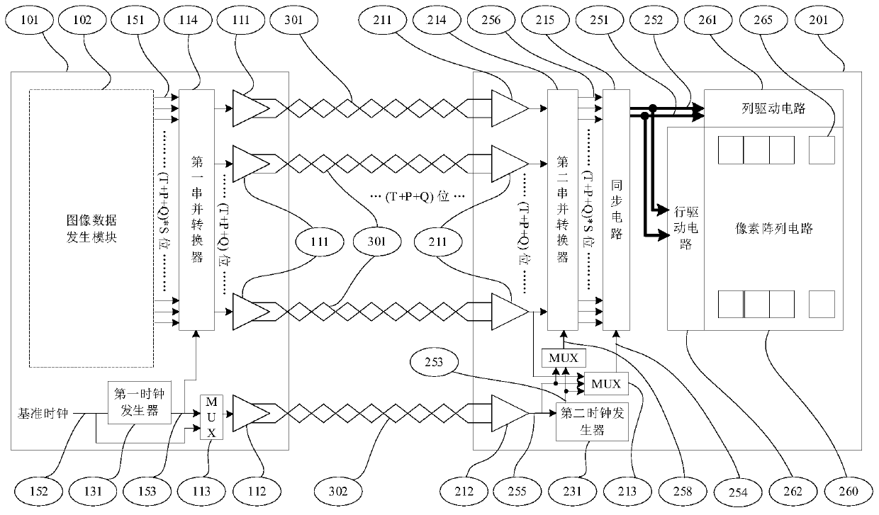
[0032] combined with figure 1 , this embodiment describes a display device with a high-speed interface.
[0033] The device includes an image generator 101 , a display 201 and a set of low-voltage differential signal transmission lines connecting the image generator 101 and the display 201 , including a first low-voltage differential signal transmission line 301 and a second low-voltage differential signal transmission line 302 .
[0034] The image generator 101 includes at least an image data generation module 102 , a first low voltage differential interface 111 , a second low voltage differential interface 112 , a first serial-to-parallel converter 114 , and a first clock generator 131 .
[0035] The display 201 includes at least a third low-voltage differential interface 211, a fourth low-voltage differential interface 212, a second serial-to-parallel converter 214, a second clock generator 231, a synchronization circuit 215, a row driver circuit 262, a column driver circui...
no. 2 example
[0047] This embodiment is basically the same as the first embodiment, the special features are:
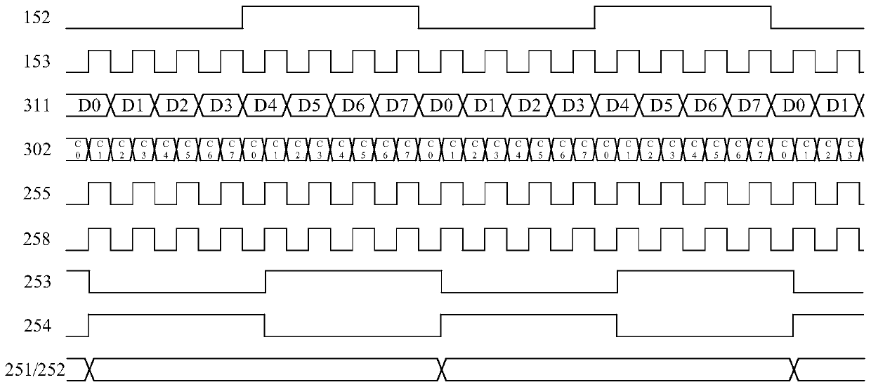
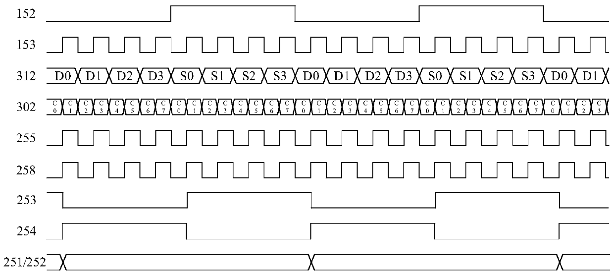
[0048] Further, both the first clock generator 131 and the second clock generator 231 are phase-locked loops, the ratio of the output clock frequency of the phase-locked loop to the output clock frequency is M / N, and both M and N are greater than or equal to 1 An integer, preferably 8-32, selected according to the internal configuration registers or input pins of the display 201 . There is a voltage-controlled oscillator inside the phase-locked loop, and both the oscillation voltage and the reference current are generated by the internal circuit of the phase-locked loop. The power supply of the phase-locked loop circuit is 1.2 ~ 3.3V. The frequency of the first output clock 153 of the first clock generator 131 is S times the frequency of the second output clock 253 of the second clock generator 231, and S is equal to M / N. The input clock (reference clock) 152 of the first clock ...
no. 3 example
[0051] This embodiment is basically the same as the first embodiment, the special features are:
[0052] Further, both the first clock generator 131 and the second clock generator 231 are phase-locked loops, the ratio of the output clock frequency of the phase-locked loop to the output clock frequency is M / N, and both M and N are greater than or equal to 1 An integer, preferably 8-32, selected according to the internal configuration registers or input pins of the display 201 . There is a voltage-controlled oscillator inside the phase-locked loop, and both the oscillation voltage and the reference current are generated by the internal circuit of the phase-locked loop. The power supply of the phase-locked loop circuit is 1.2 ~ 3.3V. The frequency of the first output clock 153 of the first clock generator 131 is S times the frequency of the second output clock 253 of the second clock generator 231, and S is equal to M / N. The input clock (reference clock) 152 of the first clock ...
PUM
 Abstract
Description
Claims
Application Information
 - R&D
- Intellectual Property
- Life Sciences
- Materials
- Tech Scout
- Unparalleled Data Quality
- Higher Quality Content
- 60% Fewer Hallucinations
Browse by: Latest US Patents, China's latest patents, Technical Efficacy Thesaurus, Application Domain, Technology Topic, Popular Technical Reports.
© 2025 PatSnap. All rights reserved.Legal|Privacy policy|Modern Slavery Act Transparency Statement|Sitemap|About US| Contact US: help@patsnap.com