Method and system for optimizing connection speed of continuous miniature straight segments

An optimization method and connection speed technology, applied in general control systems, control/regulation systems, instruments, etc., can solve problems such as poor processing quality and equipment vibration in continuous micro-line segments

Active Publication Date: 2018-11-16
SHENZHEN LEAD CNC SYST
View PDF5 Cites 9 Cited by
  • Summary
  • Abstract
  • Description
  • Claims
  • Application Information

AI Technical Summary

Problems solved by technology

[0006] In view of the above problems, the present invention proposes a method for optimizing the connection speed of continuous

Method used


Image

  • Method and system for optimizing connection speed of continuous miniature straight segments
  • Method and system for optimizing connection speed of continuous miniature straight segments
  • Method and system for optimizing connection speed of continuous miniature straight segments

Examples


Embodiment 1

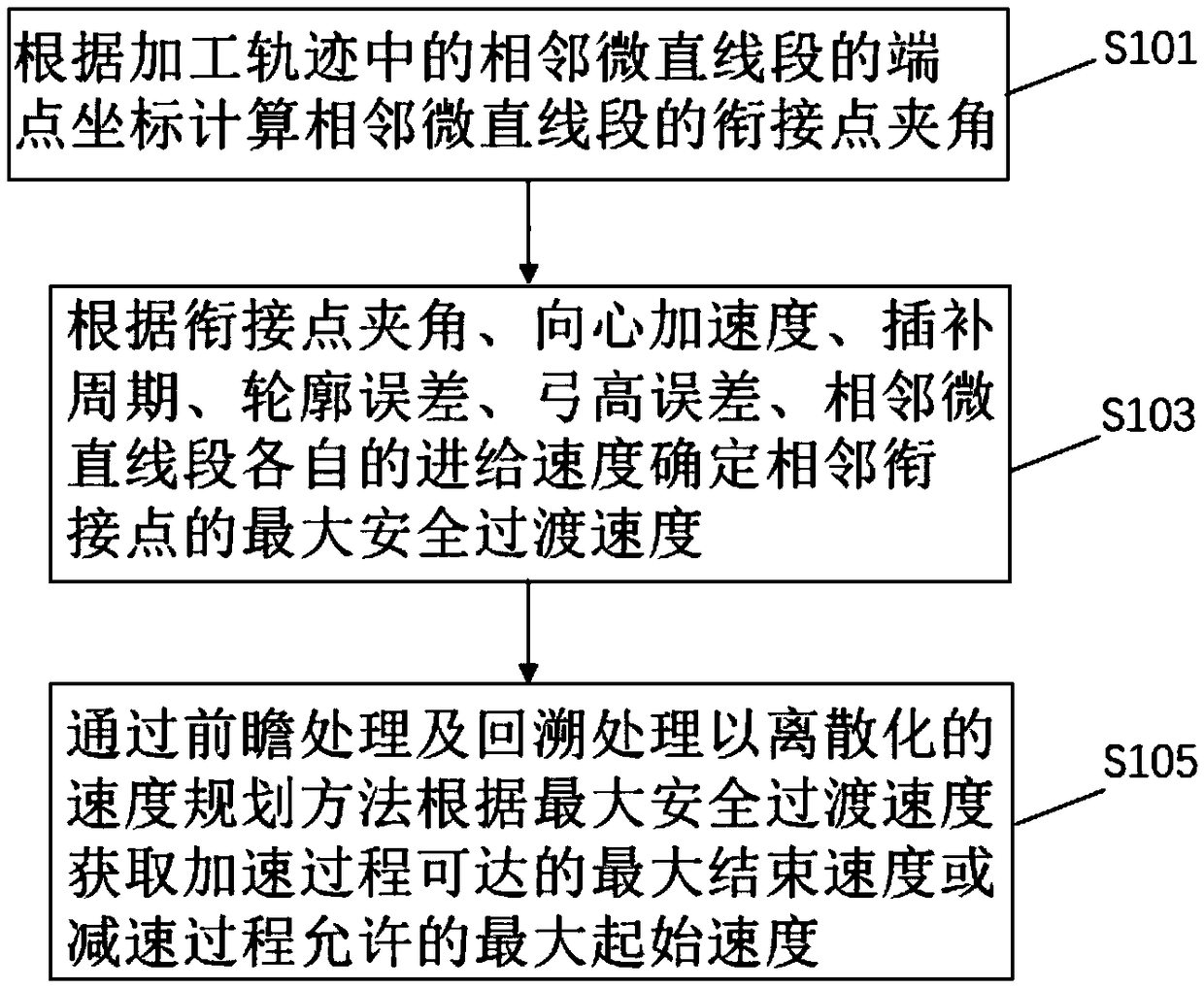
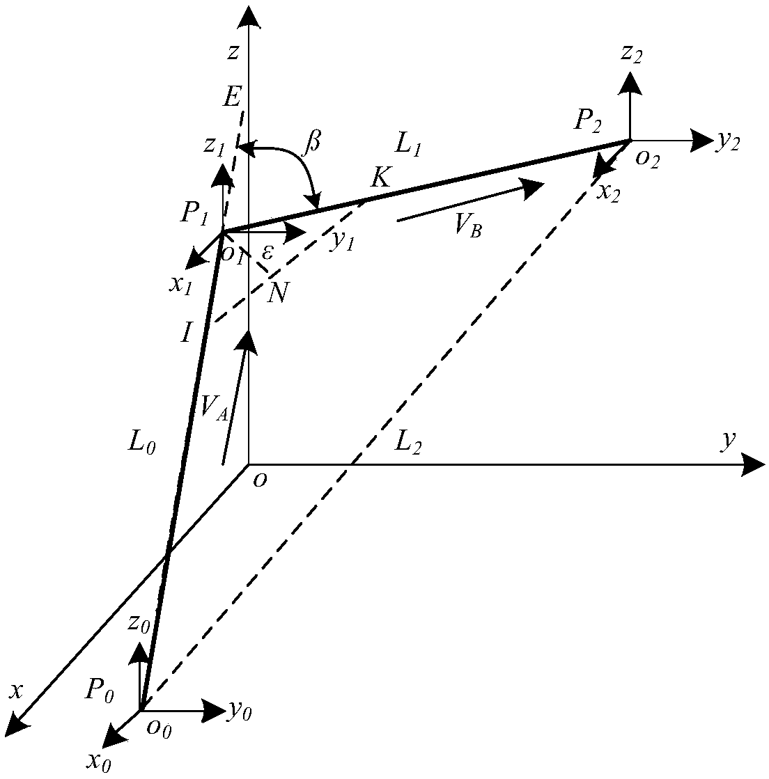
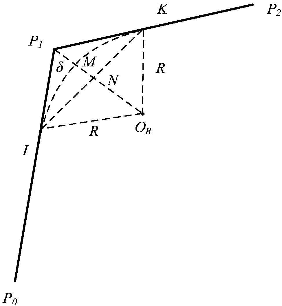
[0085] Please refer to figure 1 , Figure 1a and Figure 1b , figure 1 It is a flow chart of the method for optimizing the joint speed of continuous micro-straight line segments (hereinafter referred to as "optimization method") in Embodiment 1 of the present invention. Figure 1a It is a schematic diagram of the angle between the joint points of adjacent micro-line segments in Embodiment 1 of the present invention. Figure 1b It is a schematic diagram of the arc transition radius of the adjacent micro-straight line segments in Embodiment 1 of the present invention. Optimization methods include:

[0086] S101. Calculate the included angle of the connection point of the adjacent micro-line segments according to the end point coordinates of the adjacent micro-line segments in the machining trajectory.

[0087] exist Figure 1a , the adjacent micro-line segment P 0 P 1 and P 1 P 2 Intersect at point P1, and the coordinates of the endpoints are P 0 (x 0 ,y 0 ,z 0 ), ...

Embodiment 2

[0112] Please refer to figure 2 , figure 2 It is a flow chart of the method for optimizing the joint speed of continuous micro-straight line segments (hereinafter referred to as "optimization method") in Embodiment 2 of the present invention. Optimization methods include:

[0113] S105a, perform look-ahead initialization;

[0114] Forward initialization includes:

[0115] Set the number of forward-looking segments N and the starting speed V of the i-th segment i,s , the end velocity V of the i-th segment i,e and the displacement L of the i segment i ;

[0116] According to the initial velocity V of the i-th segment i,s , the end velocity V of the i-th segment i,e and the acceleration A of the i segment i Calculate the starting velocity V from segment i i,s to the end speed V of the i segment i,e The number of cycles n of the i-th segment required i :

[0117]

[0118] According to the cycle number n of the i-th segment i Get the actual acceleration A of the ...

Embodiment 3

[0168] Please refer to image 3 , image 3 It is a block diagram of the optimization system (hereinafter referred to as "optimization system") of the joint speed of continuous micro-straight line segments according to Embodiment 3 of the present invention. The optimization system 300 is applied to numerical control machining. Optimization system 300 includes:

[0169] Calculation module 310, the calculation module 310 calculates the angle between the joint points of adjacent micro-line segments according to the endpoint coordinates of adjacent micro-line segments in the processing trajectory;

[0170] Determination module 320, the determination module 320 determines the maximum safe transition speed of adjacent joint points according to the angle between joint points, centripetal acceleration, interpolation period, contour error, bow height error, and the respective feed speeds of adjacent micro-line segments;

[0171] Acquisition module 330, the acquisition module 330 obta...


PUM


Abstract

The invention discloses a method for optimizing a connection speed of continuous miniature straight segments, and the method comprises the steps: calculating a connection point inclined angle of the adjacent miniature straight segments according to the end coordinates of the miniature straight segments in a processing track; determining the maximum safety transition angle of the adjacent connection points according to the connection point inclined angle, a centripetal acceleration, an interpolation period, a contour error, a chord error and the respective feeding speed of the adjacent miniature straight segments; obtaining the maximum ending speed which can be reached in an accelerating process or the maximum starting speed allowed by a decelerating process according to the maximum safetytransition angle through the forward-looking processing and backtracking processing and a discretization speed planning method. The forward-looking processing and backtracking processing proposed in the embodiment are used for calculating the maximum ending speed which can be reached in the accelerating process or the maximum starting speed allowed by the decelerating process under the limiting action of the continuous miniature straight segments and the accelerating and decelerating capabilities of a machine tool, thereby effectively reducing the speed jump of the adjacent connection points.

Description

technical field [0001] The invention relates to the technical field of numerical control machining, in particular to a method and system for optimizing the joining speed of continuous micro-straight line segments. Background technique [0002] In the application scenario of complex contour parts / components processing in the field of NC machining, the data processed by NC machining is often generated by CAD / CAM software through a certain approximation criterion to discretize the contour trajectory of parts / components. Therefore, how to realize high-speed, high-precision and smooth machining of these huge numbers of discretized micro-linear segments has always been one of the goals pursued by the industry. [0003] The existing processing schemes for such discretized curvature discontinuous micro-line segments mainly include direct method and fitting method. The direct method uses each micro-line segment as the smallest unit of speed planning to directly perform trajectory in...

Claims


Application Information

Patent Timeline
IPC IPC(8): G05B19/416
CPCG05B19/4163G05B2219/35097
Inventor 吴杰文王立松蔡兴华
Owner SHENZHEN LEAD CNC SYST
Why Eureka
Try Eureka