Centrifugal blower and vacuum cleaner

a centrifugal blower and vacuum cleaner technology, which is applied in the direction of machines/engines, cleaning equipment, liquid fuel engines, etc., can solve the problems of difficult to achieve a higher output and a higher efficiency, and the air blowing efficiency of centrifugal blowers is decreased

Inactive Publication Date: 2018-04-12
NIDEC CORP
View PDF8 Cites 15 Cited by
  • Summary
  • Abstract
  • Description
  • Claims
  • Application Information

AI Technical Summary

Problems solved by technology

Accordingly, air blowing efficiency of the centrifugal blower is decreased making it difficult to achieve a higher output and a higher efficiency.

Method used


Image

  • Centrifugal blower and vacuum cleaner
  • Centrifugal blower and vacuum cleaner
  • Centrifugal blower and vacuum cleaner

Examples


Embodiment Construction

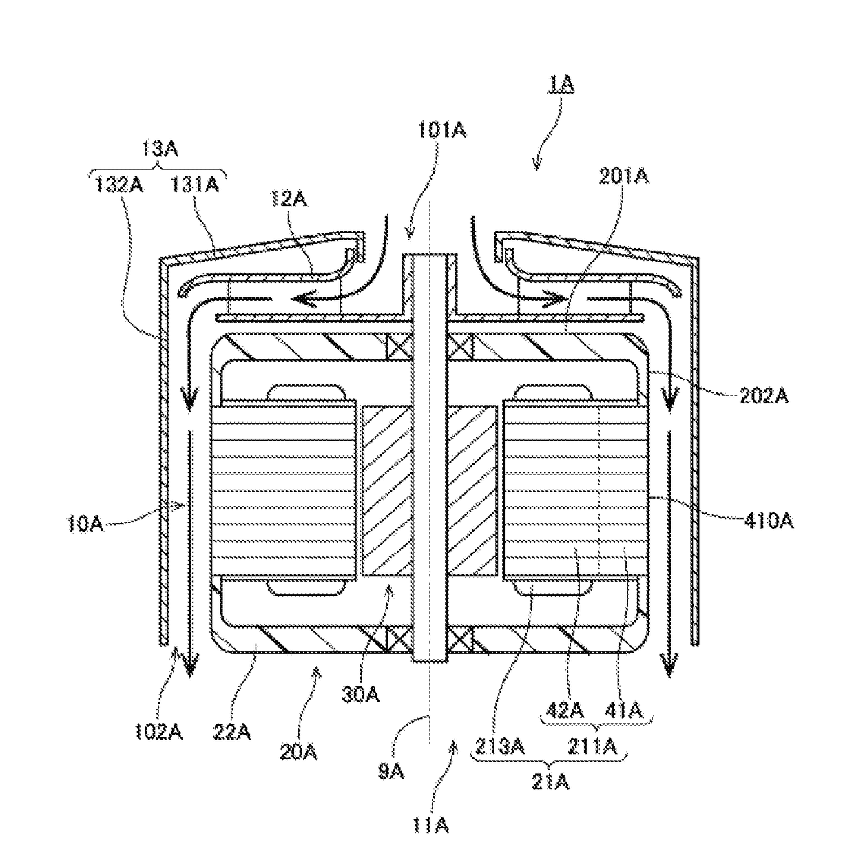
[0015]Hereinafter, a centrifugal blower according to an exemplary embodiment of the present invention will be described with reference to the drawings. Note that in the present application, a direction parallel to a central axis of a centrifugal blower is referred to as an “axial direction”, a direction orthogonal to the central axis of the centrifugal blower is referred to as a “radial direction”, and a direction along a circumference extending about a center of the central axis of the centrifugal blower is referred to as a “circumferential direction”.

[0016]Furthermore, in the present application, shapes and positional relationships of parts are described while the axial direction is an up-down direction, and an impeller side with respect to a motor is an upper side. However, the definition of the up-down direction is not intended to limit the orientations of the centrifugal blower while manufacturing and while in use.

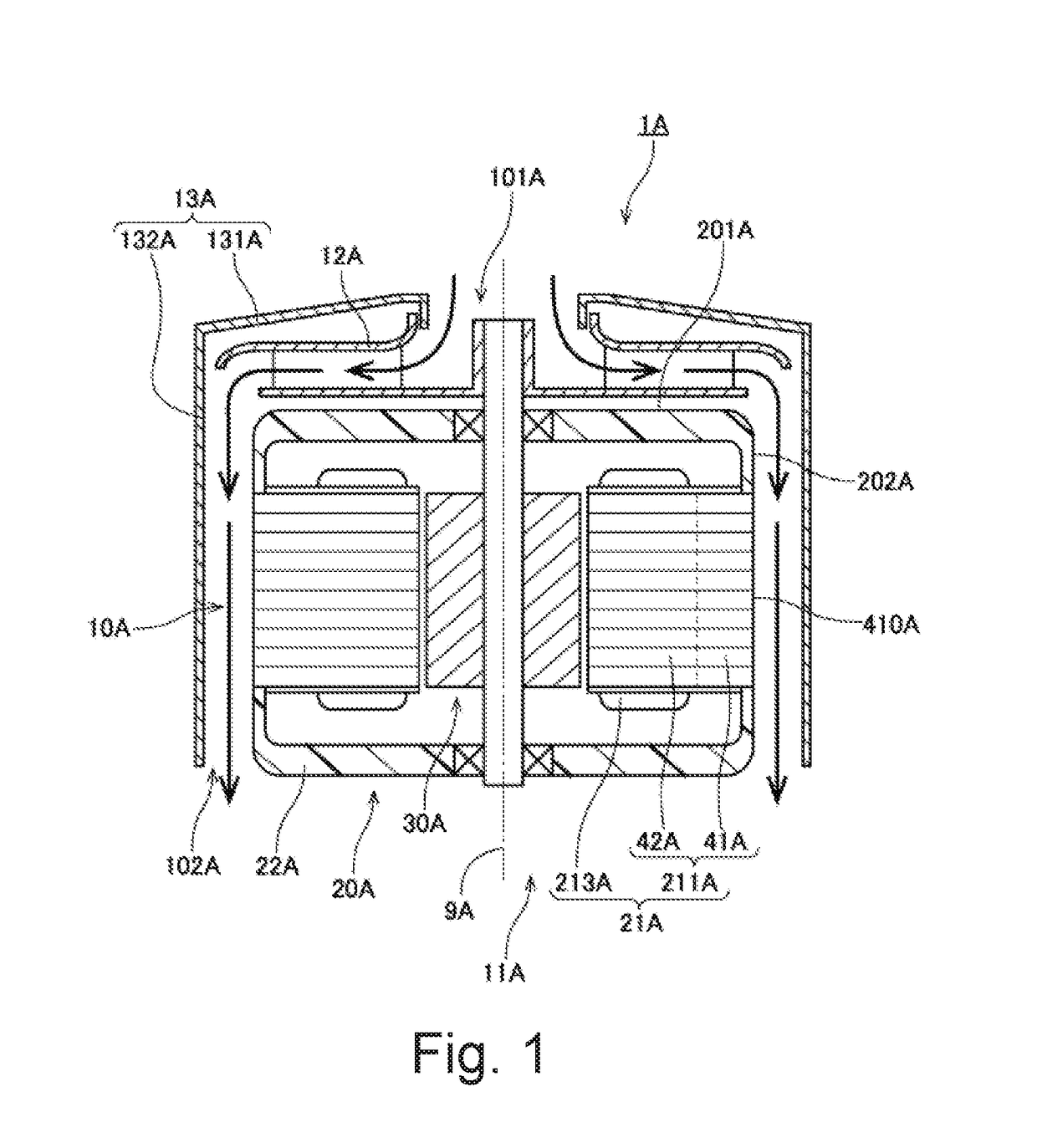
[0017]FIG. 1 is a longitudinal section of a centrifugal blower 1...


PUM


Abstract

A centrifugal blower includes a motor including a stator and a motor cover, a centrifugal impeller rotating together with a rotating portion of the motor, and a blower casing. The stator includes a stator core including a toric core back. The motor cover includes an upper surface, and a cylindrical outer peripheral surface extending downwards. The blower casing disposed above the impeller includes an upper side casing top plate portion in which an intake port is disposed at the middle, and a cylindrical wall portion extending downwards from the upper side casing top plate portion. An inner peripheral surface of the wall portion and the outer peripheral surface of the motor cover forms a flow path continuous in the axial direction. A discharge port is formed in a lower end portion of the flow path. The core back includes an exposed portion exposed to the flow path.

Description

BACKGROUND OF THE INVENTION1. Field of the Invention[0001]The present invention relates to a centrifugal blower and a vacuum cleaner.2. Description of the Related Art[0002]Conventionally, a centrifugal blower is used in high-output blowing devices, such as a vacuum cleaner and an air intake and exhaust device. The centrifugal blower includes a motor that generates driving power, an impeller that sends air, and a blower casing that houses the motor and the impeller. A conventional centrifugal blower is described in Japanese Unexamined Patent Application Publication No. 2015-59507, for example.[0003]In recent years, there is a need for higher output and higher efficiency of centrifugal blowers. In high-output blowing devices, since the rotation speed is high and a large amount of heat is generated by the stator serving as an armature, the stator needs to be cooled efficiently. In a centrifugal blower in Japanese Unexamined Patent Application Publication No. 2015-59507, a stator is coo...

Claims


Application Information

Patent Timeline
Patent Type & Authority Applications(United States)
IPC IPC(8): F04D29/58F04D25/06F04D29/46H02K9/08H02K9/06
CPCF04D29/5806F04D25/0646F04D29/464H02K9/08H02K9/06F04D29/281A47L9/0072A47L9/00F04D25/082F04D25/0606F04D17/16F04D29/444F05D2250/52F04D29/44F04D29/58F04D17/10
Inventor SAWADA, TOMOYOSHIFUKUSHIMA, MACHIKO
Owner NIDEC CORP
Why Eureka
Try Eureka