Method for configuring a real or virtual electronic control unit

Active Publication Date: 2018-04-12
DSPACE DIGITAL SIGNAL PROCESSING & CONTROL ENG
View PDF0 Cites 9 Cited by
  • Summary
  • Abstract
  • Description
  • Claims
  • Application Information

AI Technical Summary

Benefits of technology

[0057]The configuration data (containers, parameters, etc.) can only be read and edited with the active module configuration. In the inactive module configurations, redundant data storage is avoided by keeping,

Problems solved by technology

The development of control units has become a highly complex process.
In these cases it would be very laborious to reconfig

Method used


Image

  • Method for configuring a real or virtual electronic control unit

Examples


Embodiment Construction

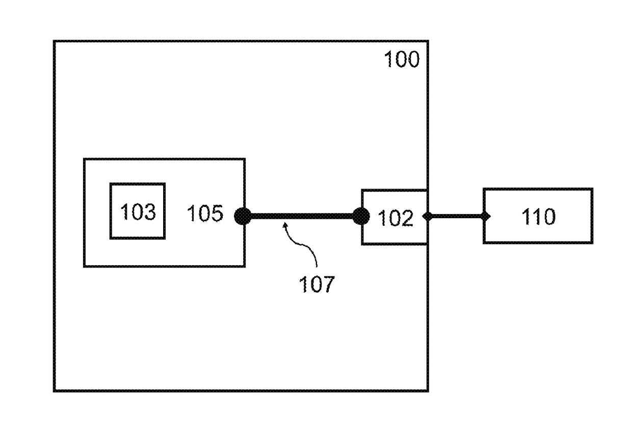
[0077]Shown in the FIGURE is a test device 100 in which a software model 103 of a technical system is executed in a computing unit 105, wherein the software model or the computing unit communicates via an input / output interface 102 of the test device and an internal data connection 107 with a device 110 connected to the test device. A computing unit can be, e.g., a processor, an FPGA, or an embedded PC. The communication with the test device can occur via the transmission of analog or digital electrical signals. The test device can comprise different hardware units (e.g., plug-in cards), which form input / output interface 102. The input / output interface and computing unit 105 form a connected system, but can also be separated spatially from one another and connected together via electronic connections.

[0078]Test device 100 can be, e.g., a “hardware-in-the-loop” (HIL) simulator. Test device 100 can also be a “rapid control prototyping” (RCP) system. The test device can also be a devic...


PUM


Abstract

A method for configuring a real or virtual electronic control unit, wherein a control unit software is executed on the control unit, and the control unit software comprises a basic software layer, the basic software layer is configured by a module configuration file by setting values of parameters, the scope of the configurable parameters being defined in a first module definition file which contains the identifiers of the configurable parameters. The first module definition file is replaced by a second module definition file, and a conversion of the first module configuration file into a second module configuration file takes place.

Description

[0001]This nonprovisional application claims priority under 35 U.S.C. § 119(a) to German Patent Application No. 10 2016 119 320.8, which was filed in Germany on Oct. 11, 2016, and which is herein incorporated by reference.BACKGROUND OF THE INVENTIONField of the Invention[0002]The present invention relates to the development of control units as they are used, e.g., in the automotive industry or in the aviation industry for controlling technical systems such as, e.g., engines or brakes, as well as to test devices used in the control unit development process.Description of the Background Art[0003]The development of control units has become a highly complex process. New control units or new control functions should thus be tested as early in the development process as possible in order to verify general functionality and to set the direction for further development. Towards the end of the development process, it is important to test the control unit, which has already undergone extensiv...

Claims


Application Information

Patent Timeline
IPC IPC(8): G06F15/78G06F11/22G05B19/02
CPCG06F15/7867G06F11/2247G05B19/02G05B2219/25065G06F11/261G05B19/042G05B2219/23446
Inventor FISCHER, SEBASTIANSUEVERN, MARKUSGEWERING, THOMASKEMPKES, BARBARA
Owner DSPACE DIGITAL SIGNAL PROCESSING & CONTROL ENG
Why Eureka
Try Eureka