Air conditioner for vehicle

a technology for air conditioners and vehicles, applied in vehicle components, vehicle heating/cooling devices, transportation and packaging, etc., can solve the problems of increased flow resistance in the passage, noise in the suction port, and difficulty in adjusting the passage to supply air to the suction port of a centrifugal fan from another direction, so as to prevent the flow speed of air, suppress the occurrence of noise and flow resistance, and prevent the effect of airflow speed

Inactive Publication Date: 2018-04-19
DENSO CORP
View PDF57 Cites 3 Cited by
  • Summary
  • Abstract
  • Description
  • Claims
  • Application Information

AI Technical Summary

Benefits of technology

[0013]Then, according to the present disclosure, the wall has the rim defining the opening and having the annular protruding portion. The annular protruding portion protrudes from the wall toward the introduction passage and covers the opening. Accordingly, the air flows in the introduction passage around the annular protruding portion and is distributed around the opening, thereby flowing to a downstream portion of the opening in the first direction. As a result, the flow speed of the air can be prevented from increasing locally in the opening and the fan suction port, whereby noise and a flow resistance can be suppressed.
[0014]Thus, the present disclosure can provide an air conditioner for a vehicle that is compact and is configured to suppress occurrences of noise and a flow resistance in a passage.

Problems solved by technology

Accordingly, it may be difficult to configure a passage to supply air to a suction port of a centrifugal fan from another direction.
As a result, an abnormality that noise is caused in the suction port and that a flow resistance in the passage increases may occur.

Method used


Image

  • Air conditioner for vehicle
  • Air conditioner for vehicle
  • Air conditioner for vehicle

Examples


Embodiment Construction

[0020]An embodiment of the present disclosure will be described hereinafter referring to drawings. The same component is assigned with the same reference number in the drawings, and a redundant explanation will be omitted, such that the following description can be understood easily.

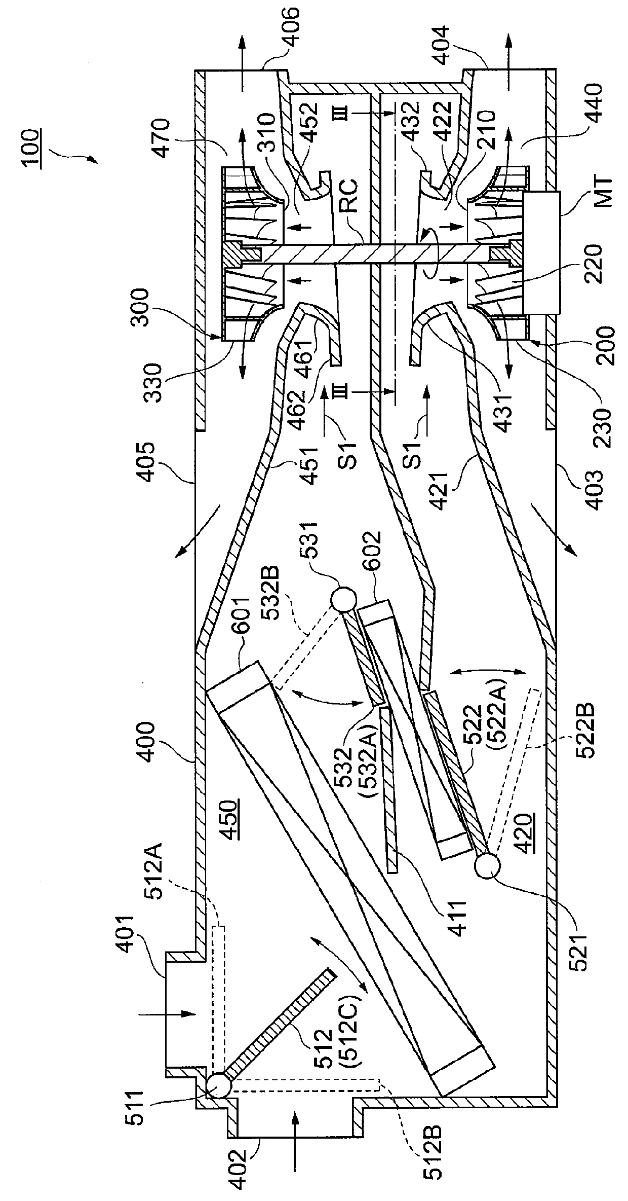
[0021]An air conditioner 100 for a vehicle according to the embodiment of the present disclosure will be described hereafter referring to FIG. 1.

[0022]The air conditioner 100 for a vehicle, referred to as the air conditioner 100 hereafter, is a device used in the vehicle to adjust a temperature of a vehicle compartment (not shown). As shown in FIG. 1, the air conditioner 100 has a housing 400, a first centrifugal fan 200, a second centrifugal fan 300, an evaporator 601, and a heater core 602.

[0023]The housing 400 is a member serving as a casing of the air conditioner 100 and is made of resin material. The housing 400 has a partition wall 411 therein. The partition wall 411 divides an inside of the housin...


PUM


Abstract

The air conditioner for a vehicle has a centrifugal fan and a housing. The centrifugal fan has a fan suction port and a rotary shaft and rotates centering on a rotational axis of the rotary shaft. The housing has a fan housing chamber, an introduction passage, and a wall. The fan housing chamber houses the centrifugal fan. The introduction passage guides air, which flows from an outside of the housing into the housing, to flow toward the centrifugal fan in a first direction intersecting with the rotational axis. The wall partitions the fan housing chamber and the introduction passage from each other and has an opening that faces the fan suction port. The wall has a rim defining the opening and being provided with an annular protruding portion. The annular protruding portion protrudes from the wall toward the introduction passage and covers the opening.

Description

CROSS REFERENCE TO RELATED APPLICATION[0001]This application is based on and claims the benefit of priority from Japanese Patent Application No 2015-091133 filed on Apr. 28, 2015. The entire disclosure of the application is incorporated herein by reference.TECHNICAL FIELD[0002]The present disclosure relates to an air conditioner for a vehicle.BACKGROUND ART[0003]An air conditioner for a vehicle is known to have a centrifugal fan and a housing. The centrifugal fan draws air in a direction along a rotational axis. The housing houses the centrifugal fan. The housing defines a passage therein. When the centrifugal fan rotates, a negative pressure is caused and thereby air is drawn into the passage from an outside or an inside of a vehicle compartment.[0004]Air conditioning devices such as an evaporator and a heater core are positioned in the passage of the housing. The air drawn into the passage passes through the air conditioning devices such that a temperature of the air is adjusted b...

Claims


Application Information

Patent Timeline
Patent Type & Authority Applications(United States)
IPC IPC(8): B60H1/00
CPCB60H1/00064B60H2001/006B60H1/00849B60H2001/00135B60H2001/00099B60H1/00471
Inventor ODA, SHUZOIMAHIGASHI, SHOUICHI
Owner DENSO CORP
Why Eureka
Try Eureka