Heat exchange promoting member and heat exchanger

A heat exchanger and component technology, applied in the field of heat exchange promoting components and heat exchangers, can solve the problems of inability to apply louver fins, no heat conduction promoting method, etc.

Pending Publication Date: 2022-05-27
株式会社爱拓制作所 +2
View PDF8 Cites 0 Cited by
  • Summary
  • Abstract
  • Description
  • Claims
  • Application Information

AI Technical Summary

Problems solved by technology

[0004] In addition, in outdoor heat exchangers used in fuel cells, gas oil water heaters, heat pump water heaters, etc., the flow rate reduction caused by the adhesion of garbage and dust is greatly affected, so it cannot be applied to heat exchangers that induce the accumulation of garbage and dust. Slit fins and louver fins in the gap do not have an effective method of promoting heat conduction

Method used


Image

  • Heat exchange promoting member and heat exchanger
  • Heat exchange promoting member and heat exchanger
  • Heat exchange promoting member and heat exchanger

Examples


Embodiment Construction

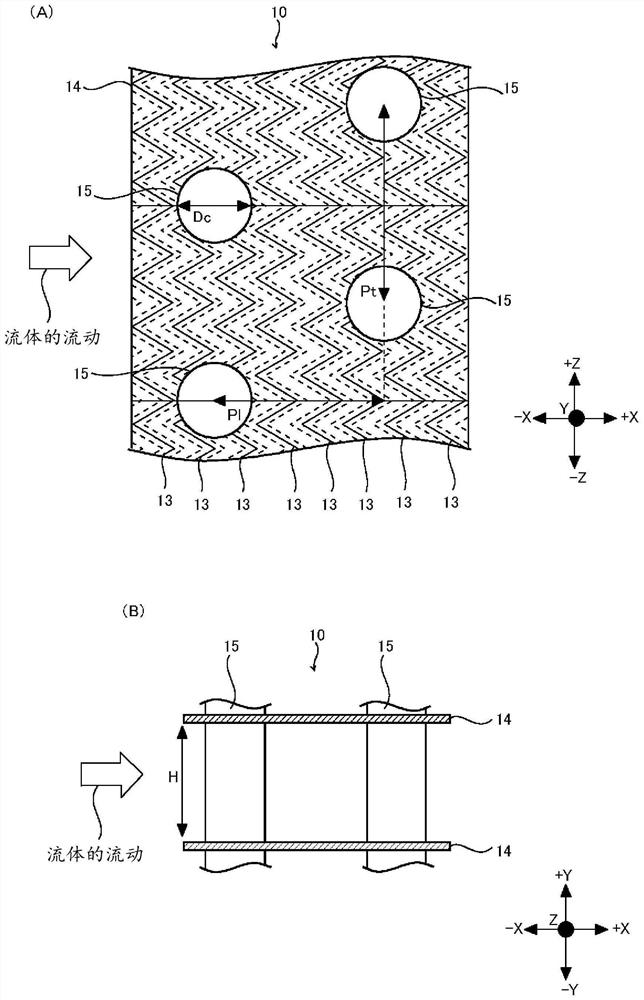
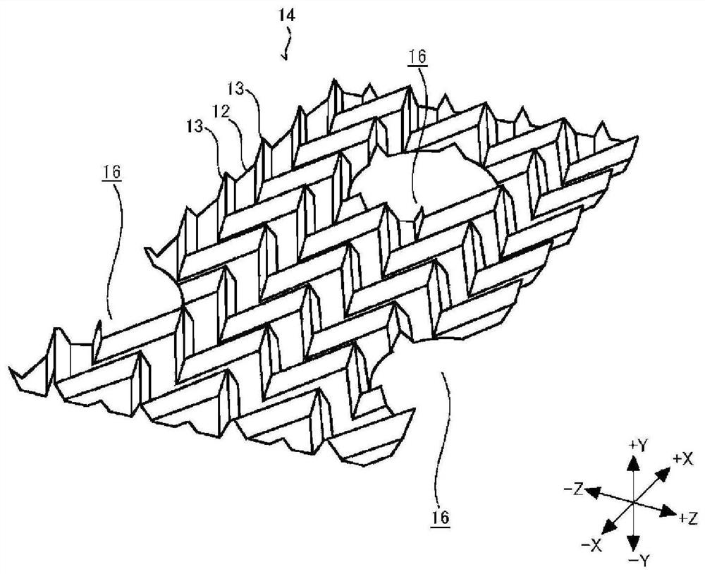
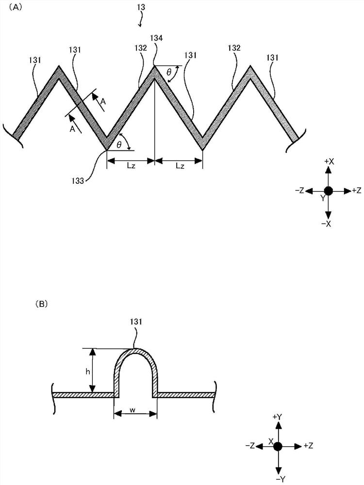
[0052] Hereinafter, embodiments of the present invention will be described in detail based on the drawings. In the following description, the case where the heat exchange promoting member of the present embodiment is applied to a fin-and-tube heat exchanger is exemplified, but the heat exchange promoting member of the present embodiment can also be applied to heat exchangers of other types, such as It can be applied to a heat transfer surface of a plate-type heat exchanger, a heat exchanger provided with a rectangular flow path, specifically, a heat transfer surface of an EGR cooler, or the like. In the following description, the X direction is a direction parallel to the direction in which the fluid flows, the Y direction is the thickness direction of the heat sink 14 , and the Z direction is a direction orthogonal to the X direction and the Y direction.

[0053] refer to figure 1 , the structure of the heat exchanger 10 will be described. figure 1 (A) is a view of the he...


PUM


Abstract

Provided are a heat exchange promoting member and a heat exchanger with which it is possible to improve thermal conductivity while suppressing an increase in pressure resistance of a fluid that exchanges heat with the heat exchange promoting member. The heat sink (14) is a heat exchange promoting member that exchanges heat with a flowing fluid. The fins (14) are provided with a planar portion (12) that is a surface substantially parallel to the direction in which the fluid flows, and a protruding portion (13) that protrudes from the planar portion (12) toward the fluid side. Furthermore, the convex parts (13) have portions inclined with respect to the direction of fluid flow, and are formed in a plurality so as to be separated from each other in the direction of fluid flow.

Description

technical field [0001] The present invention relates to a heat exchange promoting member and a heat exchanger, and particularly relates to a heat exchange promoting member and a heat exchanger capable of improving thermal conductivity while suppressing an increase in pressure resistance of a fluid in heat exchange with the heat exchange promoting member. Background technique [0002] Heat exchangers have a long history of research and development, and they have accumulated vast insights and experience in heat transfer surface design and actual machine development, both domestically and internationally. However, as a current problem, it is possible to improve the heat transfer rate beyond the increase in pressure loss due to heat transfer surface processing, and to design a heat exchanger that takes into consideration material transport properties in addition to heat transfer properties. [0003] In the conventional heat exchanger, for example, slits, louvers, etc. are formed...

Claims


Application Information

Patent Timeline
Patent Type & Authority Applications(China)
IPC IPC(8): F28F1/34F28D7/16
CPCF28F1/34F28D7/16F28F1/325F28F3/046F28F2215/04F28F3/027F28D1/03F28D1/04F28F1/32
Inventor 大友昇山本宪森本贤一铃木雄二
Owner 株式会社爱拓制作所
Why Eureka
Try Eureka