Laboratory Incubator Having Improved Moisture Distribution

a technology of incubator and humidifier, which is applied in the direction of apparatus sterilization, specific use of bioreactor/fermenter, and after-treatment of biomass, to achieve the effect of preventing the pollution of the fan, reducing the number of clogging, and increasing the resistance to flow

Active Publication Date: 2015-02-19
THERMO ELECTRONICS LED GMBH
View PDF11 Cites 32 Cited by
  • Summary
  • Abstract
  • Description
  • Claims
  • Application Information

AI Technical Summary

Benefits of technology

[0025]The precise adjustability of moisture levels in the internal chamber of the incubator according to one embodiment of the present invention prevents the moisture contained therein from condensing and forming a source of contamination. The water reservoir represents a further source of contamination. The risk of germs traveling from the water bath into the internal chamber and polluting the samples contained therein is already significantly reduced in the incubator according to the present invention by the water reservoir being arranged inside the flow channel and not immediately in the internal chamber but spatially separated therefrom. In addition, the arrangement of the water bath in the flow channel provides the facility to dispose a filter in front of and / or behind the water reservoir. Such filter disposed in front of the water reservoir in the direction of flow, prevents germs or other pollutants from being entrained into the water reservoir, thus, lengthening the intervals at which an exchange of water becomes necessary. A filter disposed behind the water reservoir in the direction of flow prevents germs or other pollutants present in the water from being conveyed by the air flowing through or across the water reservoir downstream in the direction of the at least one air outlet opening and thence into the internal chamber. If conventional HEPA or ULPA filters are used, as is fundamentally already the case in incubators, germs usually occurring inside incubators can be withheld. Less effective filters are, however, also usable, for example, in the form of membranes or other commonly used filter materials that may not guarantee sterility but do, however, retain other pollutants. Such less effective filters can be used, for example, at the water reservoir inlet. At the water reservoir outlet facing towards the internal chamber of the incubator, however, it is preferred to use HEPA or ULPA filters to prevent germs from entering the internal chamber.
[0026]A fan is appropriately utilized to cause movement of the air within the flow channel and in the internal chamber of the incubator in the manner fundamentally previously known for laboratory incubators. Such a fan can, for example, be a radial fan. Such a fan is also suitably disposed within the flow channel. It can fundamentally be mounted at any suitable location, preferably, downstream of the water reservoir and, more particularly, beyond the cold spot. To prevent pollution caused by the fan from being conveyed into the internal chamber, a filter, for example, again an air-permeable membrane, a HEPA or a ULPA filter, can be disposed downstream of the fan inside the flow channel, in particular, adjacent to the at least one air outlet opening. As excess pressure occurs in the flow channel between the fan and the filter, it is advisable for the channel to be sealed off in this region to such an extent that air cannot escape from the flow channel by passing the filter.
[0027]It is particularly appropriate to operate the fan in such a manner that a constant speed of flow prevails in the internal chamber and in the flow channel. If filters are mounted within the flow channel, the resistance to flow gradually rises with increasing allocation. For the purpose of securing a constant volumetric flow, it is, therefore, necessary to adjust the fan output accordingly, in particular, to boost it when the filters gradually become choked. This can be achieved by allocating a flow resistance meter to a filter in the flow channel and by controlling the fan output according to the measurement results obtained from such a flow resistance meter. If system disruption occurs, for example, by opening the door(s) to the internal chamber, it may be advisable to adjust the fan output. If moisture levels fall due to the door being opened, a more rapid reinstatement of the desired moisture levels may be achieved, for example, by increasing the fan output following closure of the door(s) for the purpose of increasing the intake of moisture into the internal chamber. Once the setpoint value has been reached, the fan output may be returned to the normal, lower flow rate. Furthermore, brief periods of increased fan output may be useful in the event of pollution entering the incubator, necessitating removal thereof from the system as quickly as possible via a HEPA or ULPA filter. A fan output different from the output required during normal sample storage operation may also be selected for other operational steps, for example, during a disinfecting procedure or when starting or restarting the incubator. For example, more rapid setting of the atmosphere of the internal chamber by means of increased fan output reduces the response time of the sensors and, thus, reduces the system down-time. Furthermore, sensors can be disposed at larger distances from each other, since it is possible to set like conditions more rapidly at positions set further apart. Furthermore, and for the same reason, gas inlets and corresponding gas sensors can be set at positions further apart. Conversely, in the event of a gas inlet and the corresponding sensor being set too close to each other, the fan output can be lowered to increase the system down-time. This procedure may be transferred to other sensors and measuring parameters.
[0028]Not only air, but also other gas atmospheres can be transported in the flow channel and in the internal chamber of the incubator. It is usual, for example, in so-called gassing incubators to enrich the atmosphere with carbon dioxide to achieve an acidic pH-value. This is also possible in the laboratory incubator according to the present invention. In fact, there is the particular advantage over incubators of the prior art in which it is frequently observed that moisture levels fall in an undesirable manner by adding further gases to the air. According to the present invention, this can be prevented by conducting a gas, for example, nitrogen or carbon dioxide, into the flow channel, appropriately at a point upstream of the water reservoir. As a result, before the gas enters the internal chamber of the incubator, it flows across or through the water bath, where it accumulates moisture, and is then conducted into the internal chamber with the desired moisture content, together with the air flowing in the flow channel. In this way, samples are successfully prevented from desiccation.

Problems solved by technology

However, the air flowing in the duct during normal operation of the incubator cannot flow through said orifices.

Method used


Image

  • Laboratory Incubator Having Improved Moisture Distribution
  • Laboratory Incubator Having Improved Moisture Distribution
  • Laboratory Incubator Having Improved Moisture Distribution

Examples


Embodiment Construction

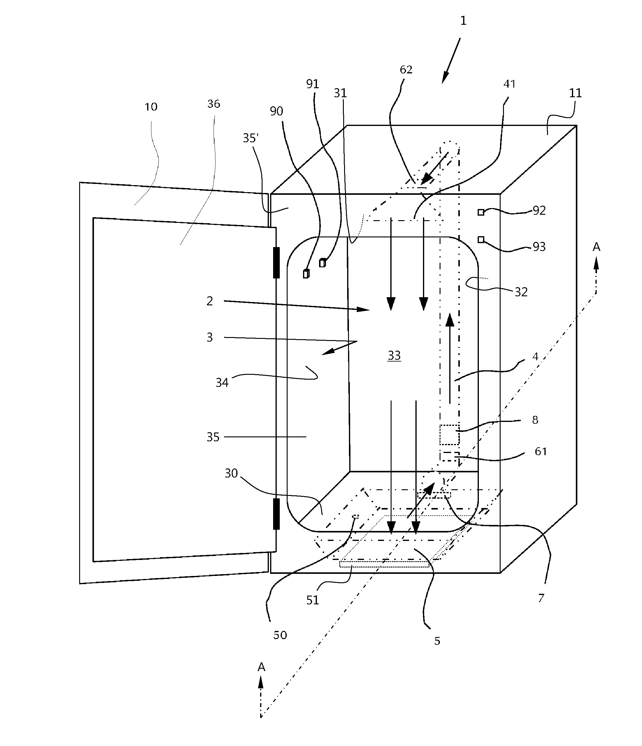
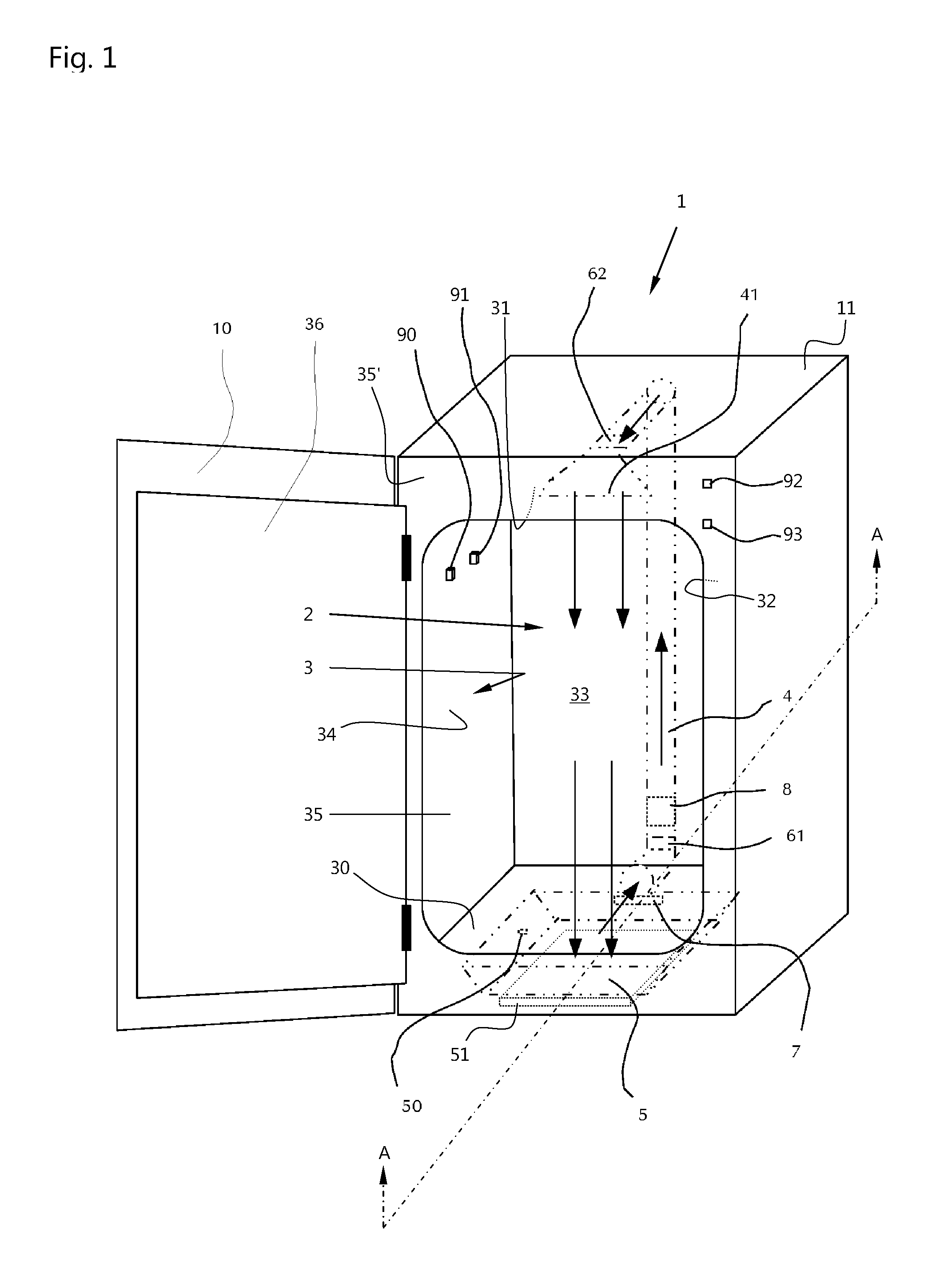
[0035]FIG. 1 shows a laboratory incubator 1 according to the present invention, in this case, by example of a gassing incubator, in a front view of the front side. The laboratory incubator comprises an outer housing 11 containing an outer door 10, enabling access to an internal chamber 2. The internal chamber 2 is enclosed by an inner housing 3 consisting of a floor 30, side wall panels 32, 33, and 34, and a ceiling panel 31. The lateral surface panel 35 facing the operator is open except for a front bezel 35′ and provides access to the internal chamber 2. The lateral surface panel 35 may be closed by means of an additional, inner door 36 made of glass, for example. In the situation illustrated, both doors 10 and 36 are shown as being open.

[0036]The internal chamber 2 serves to store samples, for example, microbiological samples, that may be stored on trays mounted inside the internal chamber. For reasons of clarity, however, samples and trays are not shown. For the purpose of stori...


PUM

PropertyMeasurementUnit
humidityaaaaaaaaaa
humidityaaaaaaaaaa
humidityaaaaaaaaaa

Abstract

The present invention relates to a laboratory incubator, more particularly, a gassing incubator, comprising an outer housing incorporating a door and an inner housing surrounding an internal chamber, which comprises a floor, a ceiling, three side walls and a lateral surface that is capable of being closed by said door or by an additional, inner door, and in which a flow channel is present, which comprises at least one air inlet opening in an end region and at least one air outlet opening in a different end region, wherein said at least one air outlet opening is formed such that effluent air is guided along at least one of the side walls and/or the lateral surface in the peripheral region of the internal chamber, and wherein a water reservoir capable of being heated is disposed within the flow channel such that air flowing in the flow channel is passed across or through said water reservoir.

Description

CROSS-REFERENCE TO RELATED APPLICATION[0001]The present application claims priority under 35 U.S.C. §119 of German Patent Application No. 10 2013 013 665.2, filed Aug. 16, 2013, the disclosure of which is hereby incorporated herein by reference in its entirety.FIELD OF THE INVENTION[0002]The present invention relates to a laboratory incubator, more particularly a gassing incubator, comprising an outer housing and an inner housing delimiting an internal chamber used for the storage of samples. The internal chamber can be accessed via a door in the outer housing. If necessary, the inner housing may comprise an additional, inner door situated adjacent to the outer door and separately closing the internal chamber. Such an inner door can, for example, be made of glass (see, U.S. Pat. No. 6,878,177 B2).BACKGROUND OF THE INVENTION[0003]Laboratory incubators usually serve to store samples, more particularly, biological and / or microbiological samples, in the internal chamber thereof, under p...

Claims


Application Information

Patent Timeline
Patent Type & Authority Applications(United States)
IPC IPC(8): C12M1/00C12M1/12B01L1/02
CPCC12M41/14B01L1/025B01L2300/10C12M23/34C12M37/02C12M29/26B01L2200/146B01L2200/147B01L2300/043B01L2300/0829
Inventor PIECZAREK, WALDEMARSCHNEIDER, JUERGEN ANDREASSTAHL, HERMANN
Owner THERMO ELECTRONICS LED GMBH
Why Eureka
Try Eureka