fuel oil transfer system
A fuel oil and fuel technology, which is applied in the direction of charging system, pipeline system, fuel heat treatment device, etc., can solve the problems of not considering the transfer of objects with the same properties as fuel oil, which is not conducive to energy saving of fuel consumption and waste, and achieves suppression Effect of flow resistance and smooth transfer
Active Publication Date: 2019-10-01
HOKUSHIN ENG
View PDF8 Cites 0 Cited by
- Summary
- Abstract
- Description
- Claims
- Application Information
AI Technical Summary
Problems solved by technology
However, the structure disclosed in Patent Document 1 is only based on the premise of selecting any one of a plurality of tanks, and does not consider the transfer of objects having the same properties such as fuel oil between tanks.
Therefore, since the small amount of fuel oil remaining in the tank is left intact without being consumed, it is not conducive to implementing energy-saving measures to suppress wasteful fuel consumption.
Method used
View moreImage
Smart ImageViewing Examples
Examples
Embodiment Construction
Login to View More PUM
 Abstract
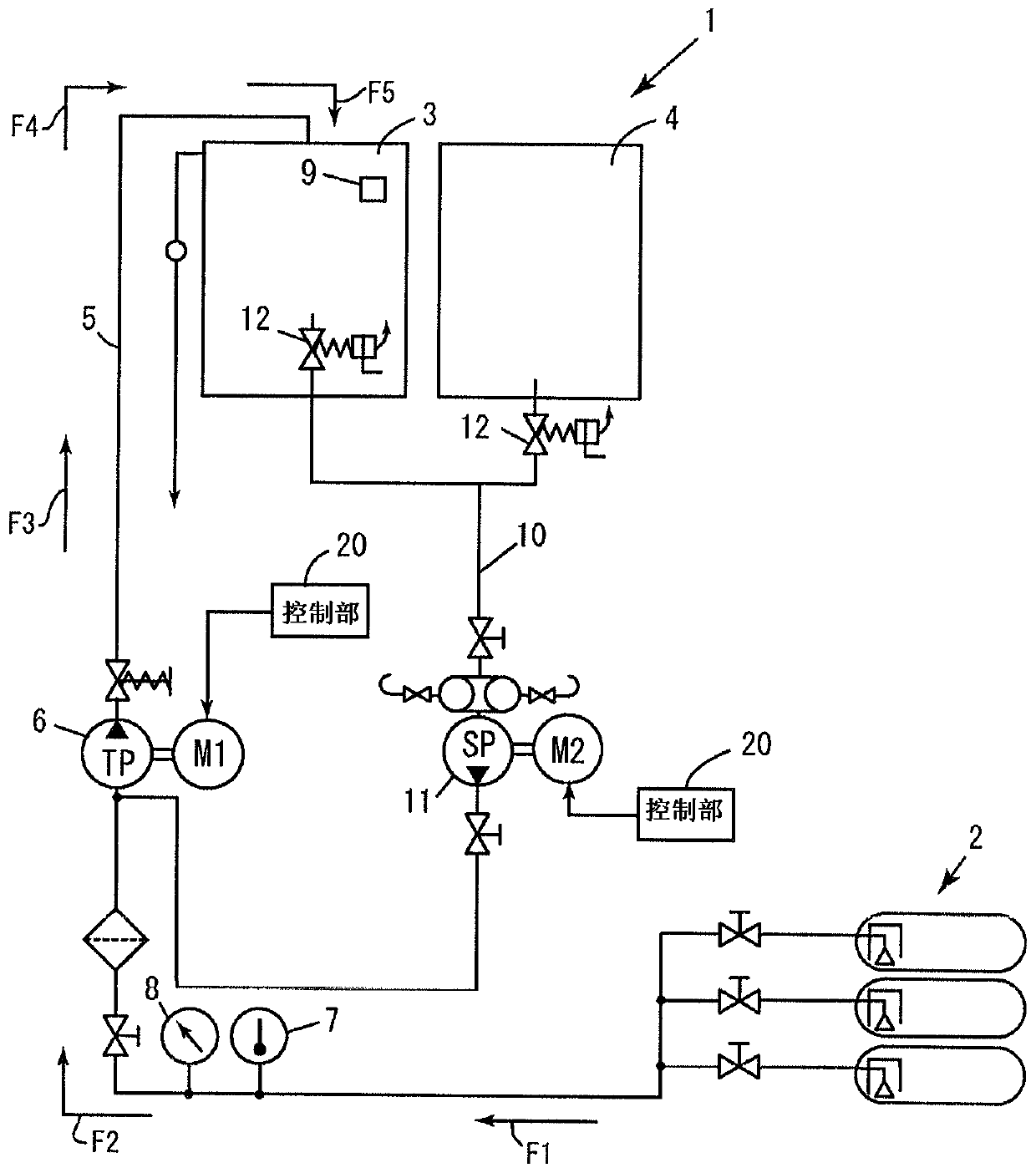
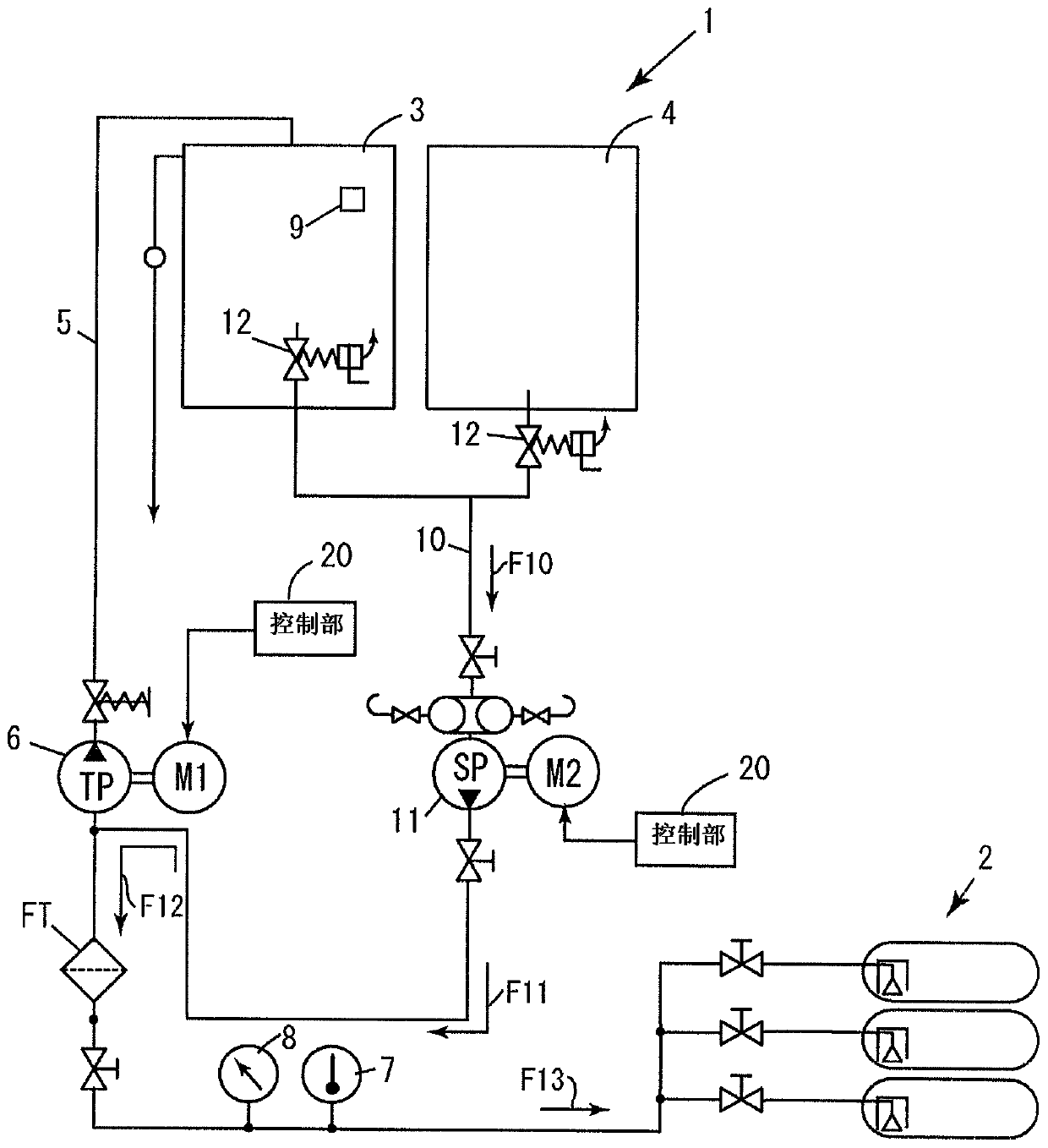
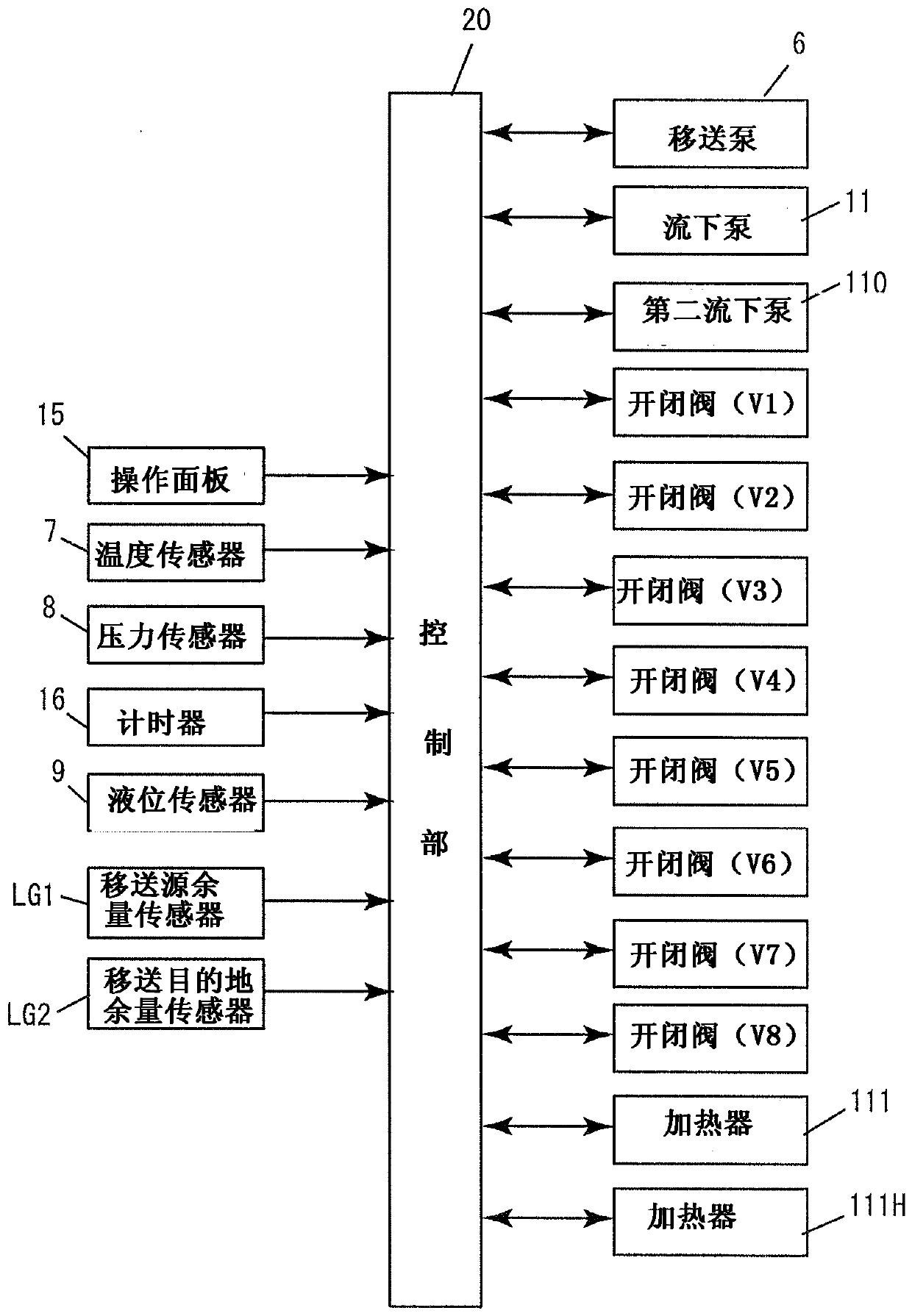
The invention provides a transfer system of fuel oil, being able to suppress waste when the fuel oil stored in a plurality of tanks is consumed. The transfer system of fuel oil is characterized in that in a transfer path on which the fuel oil in a fuel oil gun barrel is used to preheat a fuel oil storage tank (2B) as a transfer destination, a first auxiliary inflow pipe (10) is used to discharge the oil from a transfer pump (6), and in a transfer path on which the fuel oil in a fuel oil storage tank (2A) as a transfer source is transferred to the fuel oil storage tank (2B) as the transfer destination, a second auxiliary inflow pipe (200) and a pass-over fuel oil path (101) are used, and when the fuel oil is transferred to the fuel oil storage tank as the transfer destination from the transfer source, one part of the fuel oil passing the second auxiliary inflow pipe (200) back flows to the transfer pump (6) side by passing the first auxiliary inflow pipe (10).
Description
Technical field The present invention relates to a fuel oil transfer system, and more specifically, to a fuel oil transfer system for transferring fuel oil between fuel oil storage tanks. Background technique Fuel oil used in boilers such as ships and generators is stored in storage parts such as tanks and is supplied to internal combustion engines for consumption. In addition, in addition to fuel oil, lubricating oil targeted at a host such as an internal combustion engine is also stored in a storage section such as a tank for use in the same way as fuel oil. There are cases in which a plurality of tanks are prepared for storage of fuel oil and lubricating oil used in ships, depending on the type of properties or different storage amounts (for example, Patent Document 1). Patent Document 1 discloses a structure in which when replenishing lubricating oil reduced by consumption by an internal combustion engine, one of a plurality of tanks storing lubricating oil having differen...
Claims
Login to View More Application Information
Patent Timeline
 Patent Type & Authority Patents(China)
IPC IPC(8): F17D1/14
CPCF17D1/14B63H21/38B67D7/04B67D7/58B67D7/78B67D7/82F02M31/125F02M31/16
Inventor 千千波孝泰
Owner HOKUSHIN ENG
Features
- R&D
- Intellectual Property
- Life Sciences
- Materials
- Tech Scout
- Unparalleled Data Quality
- Higher Quality Content
- 60% Fewer Hallucinations
Learn More Browse by: Latest US Patents, China's latest patents, Technical Efficacy Thesaurus, Application Domain, Technology Topic, Popular Technical Reports.
© 2025 PatSnap. All rights reserved.Legal|Privacy policy|Modern Slavery Act Transparency Statement|Sitemap|About US| Contact US: help@patsnap.com


