Image capturing apparatus, controlling method for image capturing apparatus, and storage medium

Active Publication Date: 2018-04-19
CANON KK
View PDF4 Cites 1 Cited by
  • Summary
  • Abstract
  • Description
  • Claims
  • Application Information

AI Technical Summary

Benefits of technology

The present invention is an image capturing apparatus that can detect and correct defective pixels in captured images. It includes an image capturing element, a first obtaining unit, a second obtaining unit, a first detecting unit, a second detecting unit, and a correcting unit. The first obtaining unit obtains a pixel value of a first image through the image capturing element. The second obtaining unit obtains a pixel value of a second image for autofocus. The first detecting unit detects defective pixels in the first image based on the pixel value of the first image. The second detecting unit detects a defective pixel based on information of the defective pixel detected by the first detecting unit and the pixel value of the second image. The correcting unit corrects the second image by replacing the pixel value of the defective pixel with the pixel value of another normal pixel in the second image. This invention allows for improved image quality and reduced defective pixel output from the image capturing apparatus.

Problems solved by technology

Although this system is simple, it has a problem of requiring time.
On the other hand, since the image capturing element contains a defective pixel having an abnormal output and the defective pixel like this affects ranging performance of the image capturing surface phase difference AF, it is necessary to correct a defect (or flaw).

Method used


Image

  • Image capturing apparatus, controlling method for image capturing  apparatus, and storage medium
  • Image capturing apparatus, controlling method for image capturing  apparatus, and storage medium
  • Image capturing apparatus, controlling method for image capturing  apparatus, and storage medium

Examples


first embodiment

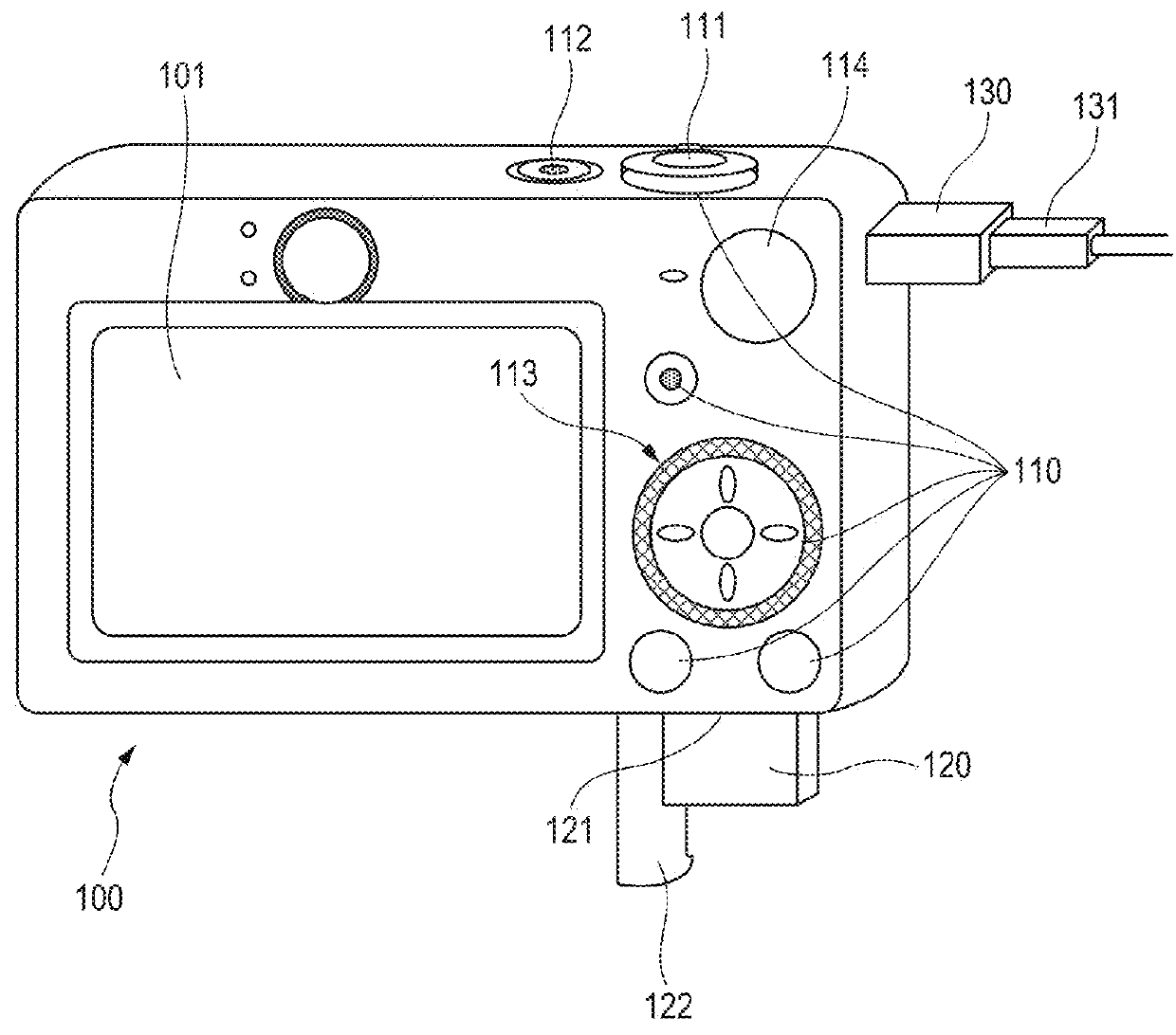
[0021]First, a hardware constitution of a digital camera 100 which is an example of an image capturing apparatus will be described with reference to FIG. 1. Namely, FIG. 1 is the appearance diagram of the digital camera 100.

[0022]A displaying unit 101 is a displaying unit which displays images and various kinds of information.

[0023]An operating unit 110 is constituted by operation members such as various switches, various buttons, a touch panel and the like for accepting various operations from a user. Besides, the operating unit 110 comprises a shutter button 111, a mode changeover switch 114, a power supply switch 112 and a controller wheel 113.

[0024]The shutter button 111 is an operating unit for generating a photographing instruction.

[0025]The power supply switch 112 is a switch which is used for an operation of changing over a power state between power on and power off for the digital camera 100.

[0026]The controller wheel 113 is a rotatable operation member which is included in...

second embodiment

[0190]Subsequently, a second embodiment of the present invention will be described. In the present embodiment, the same components as those in the first embodiment are denoted respectively by the same reference numerals, and detailed descriptions thereof will be omitted.

[0191](Constitutions of Image Processing Unit and System Controlling Unit)

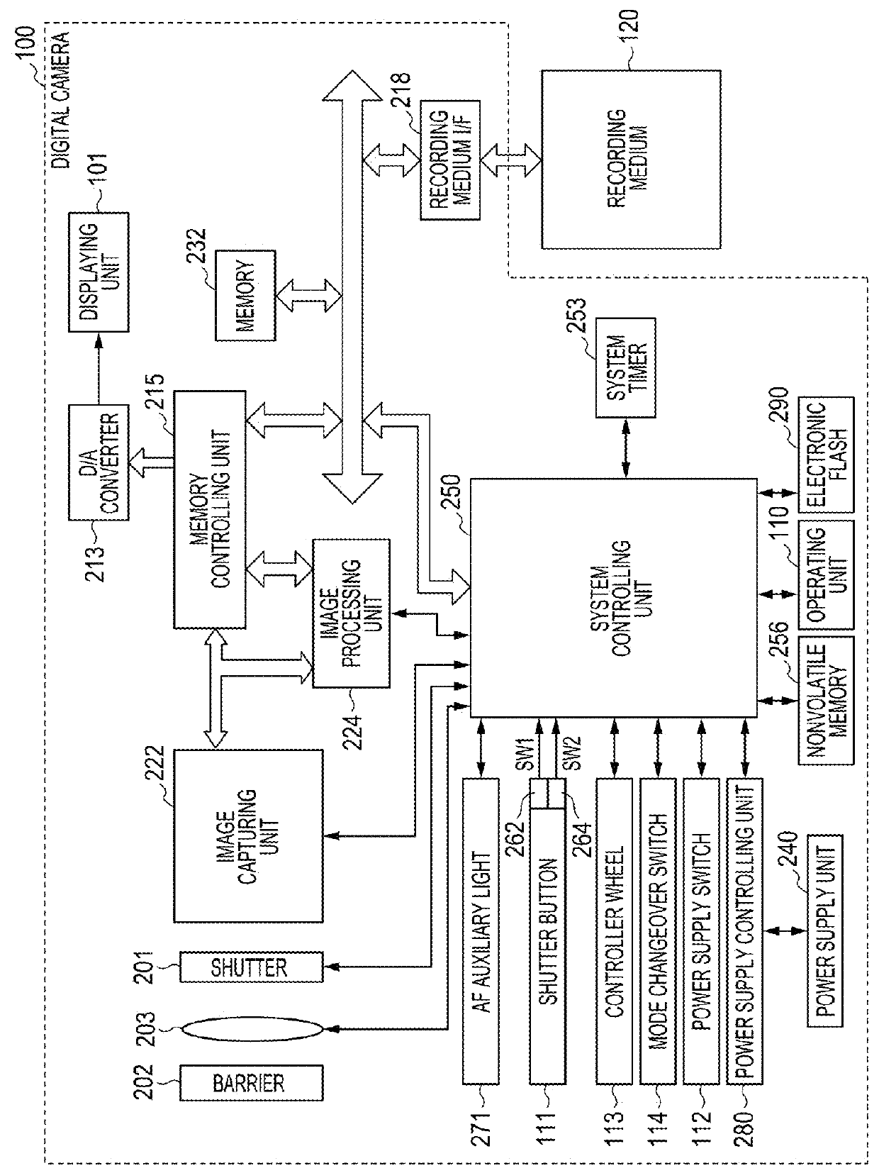
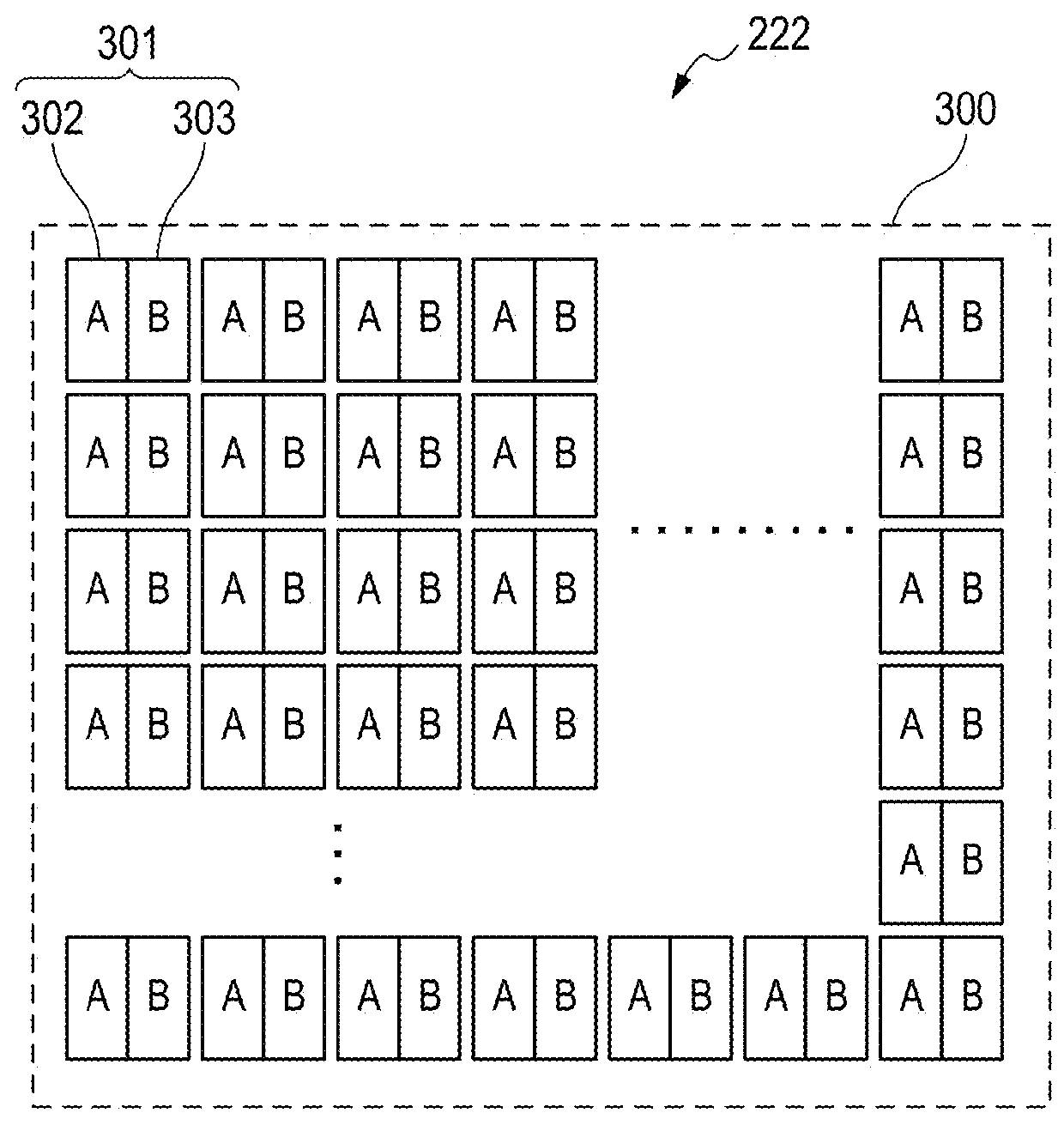
[0192]Constitutions of the image processing unit 224 and the system controlling unit 250 according to the second embodiment will be described with reference to FIG. 12. The present embodiment is different from the first embodiment in the point that the image processing unit 224 comprises a defect information memory 420. As well as the first embodiment, under the control of the system controlling unit 250, the image separating unit 400 reads a signal from the image capturing element 300 constituting the image capturing unit 222, and outputs an A image, a B image, and a pixel value of an addition image. The image separating unit 400 separates the...

third embodiment

[0195]Subsequently, a third embodiment of the present invention will be described. In the present embodiment, the same components as those in the first embodiment and the second embodiment are denoted respectively by the same reference numerals, and detailed descriptions thereof will be omitted.

[0196](Constitution of Image Processing Unit and System Controlling Unit)

[0197]The constitutions of the image processing unit 224 and the system controlling unit 250 according to the third embodiment will be described with reference to FIG. 13. The present embodiment is different from the first embodiment in the point that the image processing unit 224 comprises the defect information memory 420 as well as the second embodiment, and the present embodiment is different from the second embodiment in the point that the image processing unit 224 does not comprise the image separating unit 400. Besides, an image capturing unit 22 is configured to be able to simultaneously output two systems of ima...


PUM


Abstract

To perform high-accurate correction while securing high-speed process, an image capturing apparatus comprises: an image capturing element having plural unit pixels; a first obtainer obtaining a pixel value of a first image generated by a first method, based on an output signal of the image capturing element; a second obtainer obtaining a pixel value of a second image for autofocus generated by a second method different from the first method, based on the output signal of the image capturing element; a first detector detecting a defective pixel based on the pixel value of the first image; a second detector detecting a defective pixel based on information of the defective pixel detected by the first detector and the pixel value of the second image; and a corrector correcting the second image, by correcting the pixel value of the second image corresponding to the defective pixel detected by the second detector.

Description

BACKGROUND OF THE INVENTIONField of the Invention[0001]The present invention relates to an image capturing apparatus, a controlling method for controlling the image capturing apparatus, and a storage medium of storing a program for controlling the image capturing apparatus.Description of the Related Art[0002]In recent years, image capturing equipment (imaging equipment, image pickup equipment) such as a home video camera, a digital still camera and the like has been widely spread. In general, each of these cameras has an AF (autofocus) function for automatically adjusting a focus position of a lens, so that a user can perform photographing (shooting, filming) by leaving the camera to adjust the focus position without doing so himself. This function is beneficial to the user.[0003]Incidentally, an AF mechanism using an image capturing element is roughly classified into two kinds, that is, a contrast AF method and an image capturing surface phase difference AF method. In the contrast ...

Claims


Application Information

Patent Timeline
IPC IPC(8): H04N5/232H04N5/367
CPCH04N5/23212H04N5/3675H04N5/23293H04N23/67H04N23/63H04N25/683H04N25/134
Inventor OKUBO, TOSHIYUKI
Owner CANON KK
Why Eureka
Try Eureka