Apparatus and Method to Optimize Pacing Parameters

a technology of pacing parameters and apparatus, applied in the field of implantable medical devices, can solve the problems of ventricular dyssynchrony, nearly one third of crt candidates fail to respond to therapy as intended, and the pump function of the heart is inefficient,

Inactive Publication Date: 2018-04-26
BIOTRONIK SE & CO KG
View PDF9 Cites 2 Cited by
  • Summary
  • Abstract
  • Description
  • Claims
  • Application Information

AI Technical Summary

Benefits of technology

[0023]It is an objective of the present invention to provide a heart stimulator comprising a stimulation control unit and one or more stimulation units that can determine beneficial pacing parameters. The present invention thus targets a means for addressing patient populations that show no meaningful clinical response to CRT therapies.

Problems solved by technology

If the myocardium is fully depolarized it is unsusceptible to further excitation and is thus refractory.
Where AV synchrony exists, the heart functions more efficiently as a pump for circulating blood within the patient's anatomy; where AV synchrony is absent, the heart functions as an inefficient pump (largely because the right ventricle is contracting when it is not filled with blood).
Such circumstances create ventricular dyssynchrony where contraction in the ventricles no longer coordinates to enable efficient cardiac output.
Despite these noted therapeutic gains, clinical experience has shown that nearly one third of CRT candidates fail to respond to the therapy as intended.
The introduction of CRT in the late 1990s generated further interests in AVD optimization and brought on a new challenge for VVD optimization, which aims to coordinate RV and LV contractions.
Moreover, AVD and VVD optimizations have been further complicated by additional confounding factors, which include their variations subject to the pacing rate and the pacing mode.
Alternatively, if the AVD is too long, the ventricle contracts well after the closure of the atrioventricular valve causing a concomitant reduction in the potential benefit offered from the atrial kick.
Additionally, in cases of excessive AVD, backflow of blood from the ventricle into the atrium, i.e., mitral regurgitation, proves likely, further reducing cardiac output.

Method used


Image

  • Apparatus and Method to Optimize Pacing Parameters
  • Apparatus and Method to Optimize Pacing Parameters
  • Apparatus and Method to Optimize Pacing Parameters

Examples


Embodiment Construction

[0083]The following description is of the best mode presently contemplated for carrying out the present invention. This description is not to be taken in a limiting sense, but is made merely for the purpose of describing the general principles of the present invention. The scope of the present invention should be determined with reference to the claims.

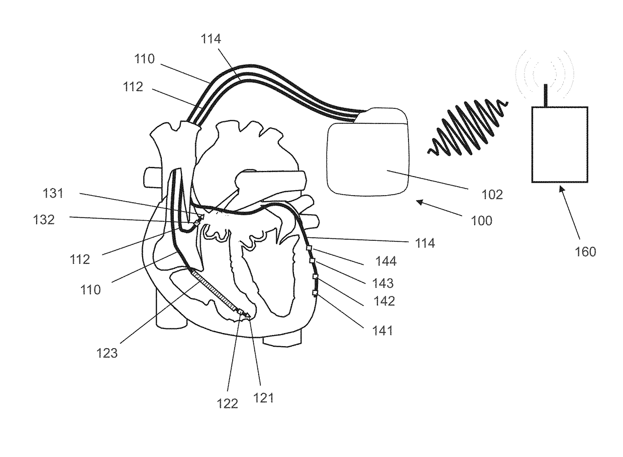
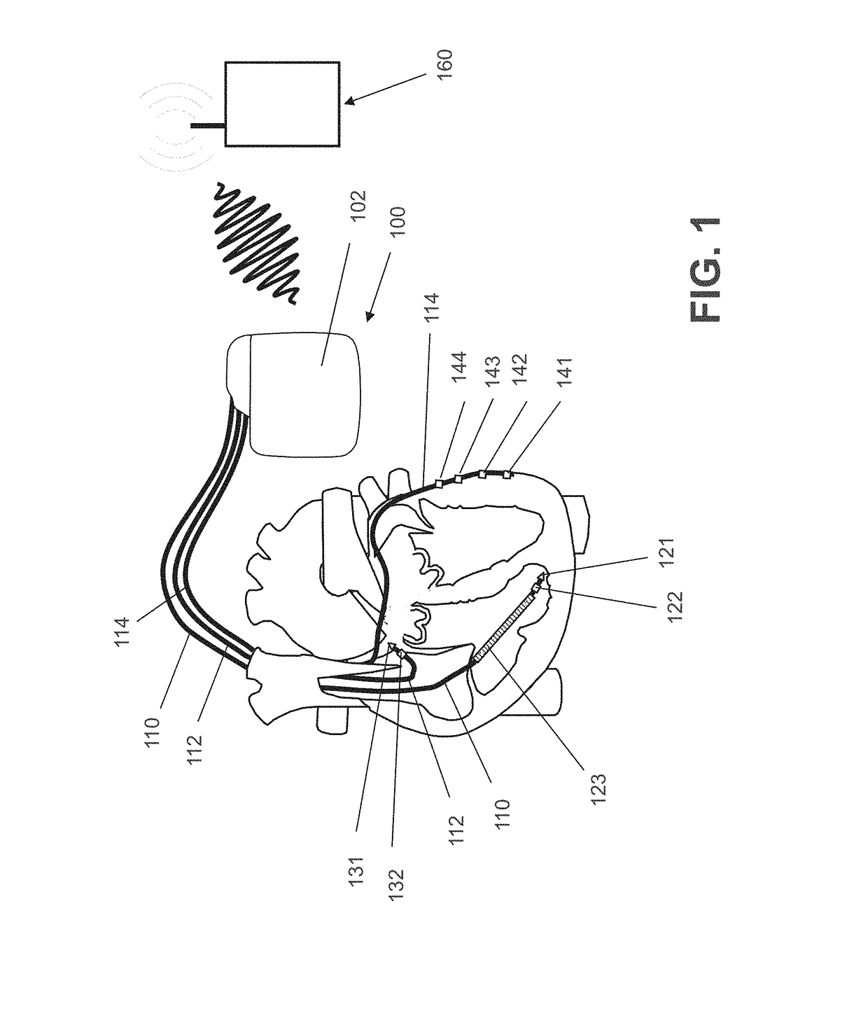
[0084]In FIG. 1 the implantable medical device (also referred to as implantable cardiac device) is a three chamber biventricular pacemaker and cardioverter / defibrillator 100 that is connected to pacing / sensing leads 110, 112 and 114 placed in a heart is illustrated.

[0085]As shown in FIG. 1, the preferred embodiment is to couple the disclosed technology with an implantable bi-ventricular defibrillator.

[0086]The implantable medical device 100 is electrically coupled to heart by way of leads 110, 112 and 114.

[0087]Lead 110 is a right ventricular electrode lead that has a pair of ventricular stimulation and sensing electrodes 121 and 122 ...


PUM


Abstract

An implantable medical device including a control unit, at least a right ventricular sensing unit and/or a right atrial sensing unit, wherein the right ventricular sensing unit is connected or can be connected to a right ventricular stimulation electrode lead having at least one electrode pole and a stimulation unit that is connected or can be connected to a multipolar left ventricular stimulation electrode lead having a plurality of electrode poles. The control unit is adapted to determine right atrioventricular conduction state and to cause selection of one of the plurality of electrode poles of the multipolar left ventricular stimulation electrode lead depending a respective determined right atrioventricular conduction state.

Description

CROSS-REFERENCE TO RELATED APPLICATIONS[0001]This patent application claims the benefit of co-pending U.S. Provisional Patent Application No. 62 / 410,417, filed on Oct. 20, 2016, which is hereby incorporated by reference in its entirety.TECHNICAL FIELD[0002]The present invention refers to an implantable medical device comprising a control unit, and at least a right ventricular sensing unit that is connected, or can be connected, to a right ventricular stimulation electrode lead having at least one electrode pole and a stimulation unit that is connected, or can be connected, to a multipolar left ventricular stimulation electrode lead having a plurality of electrode poles.[0003]The present invention particularly refers to a heart stimulator intended to administer cardiac resynchronization therapy (CRT). Such a heart stimulator can embody an implantable cardiac pacemaker or similar functionality as enabled via implantable cardiac cardioverter / defibrillator devices.[0004]Cardiac resynchr...

Claims


Application Information

Patent Timeline
Patent Type & Authority Applications(United States)
IPC IPC(8): A61N1/362A61N1/37A61B5/00A61N1/372
CPCA61N1/3622A61N1/3712A61B5/686A61N1/372A61N1/3684A61N1/3686A61N1/371A61N1/362A61N1/3714A61N1/368
Inventor TAFF, BRIAN M.
Owner BIOTRONIK SE & CO KG
Why Eureka
Try Eureka