Balanced rotary engine

a rotary engine and balance technology, applied in the direction of reciprocating piston engines, machines/engines, positive displacement engines, etc., can solve the problems of few custom-made machines, and achieve the effects of reducing the number of parts, generating significant torque, and reducing the size of the cubicl

Inactive Publication Date: 2018-04-26
QUEBEC ENGINE TECH LLC
View PDF2 Cites 0 Cited by
  • Summary
  • Abstract
  • Description
  • Claims
  • Application Information

AI Technical Summary

Benefits of technology

[0011]I now have designed a novel and unobvious balanced rotary engine, which significantly reduces, or essentially eliminates, the problems described above. My new rotary engine is about half the weight of other engines of the same cubic size (volume) because of its reduced number of parts. Advantageously, for this reduced cubic size, the rotary engine is able to generate significant torques and with that an improved fuel consumption efficiency. These two significant advantages are achieved because the engine operates almost “friction free”. Furthermore, the rotary engine, again because of reduced part numbers has low vibration levels. The only vibration that exists is the pulse of the fuel combustion. In conventional internal combustion engines, specifically of the rotary engine type, the energy produced during rotation is generally applied to the side of the cylinder. In my new rotary engine, this energy transmits to the twin crankshaft. Twin connection rods or arms cause reduced piston side load. Furthermore, at the piston head, several thin compression rings provide low friction and eliminate the need to drive cams with heavy springs. In sum, the reduced friction and vibration translate into improved energy output with lower fuel consumption. To date in tests I have performed, my new rotary engine provides 38.6% fuel efficiency, which is unprecedented for an engine of this size. As mentioned above, of all the four stroke engines I know, the new rotary engine has the fewest parts count. From a manufacturing point of view, the reduced number of parts is significant, not only for reduced cost, but also for easy, fast and accurate assembly. Moreover, the parts used in the new rotary engine are mostly available for existing rotary engines. Indeed, of the parts used, few require custom manufacture. Finally, the reduction in parts has an additional operational advantage. Translation of rotational energy (torque) to a direct drive shaft does not need a reduction gearbox, which would ordinarily need more parts and therefore add weight to the engine.

Problems solved by technology

Indeed, of the parts used, few require custom manufacture.

Method used


Image

  • Balanced rotary engine
  • Balanced rotary engine
  • Balanced rotary engine

Examples


Embodiment Construction

Definitions

[0121]Unless otherwise specified, the following definitions apply:

[0122]The singular forms “a”, “an” and “the” include corresponding plural references unless the context clearly dictates otherwise.

[0123]As used herein, the term “comprising” is intended to mean that the list of elements following the word “comprising” are required or mandatory but that other elements are optional and may or may not be present.

[0124]As used herein, the term “consisting of” is intended to mean including and limited to whatever follows the phrase “consisting of”. Thus, the phrase “consisting of” indicates that the listed elements are required or mandatory and that no other elements may be present.

1. General Rotary Engine Construction

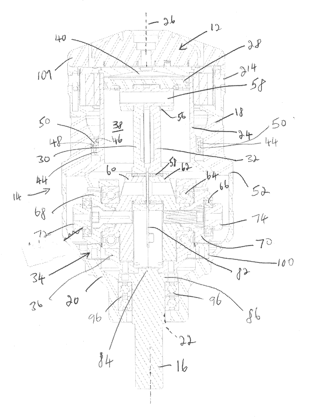
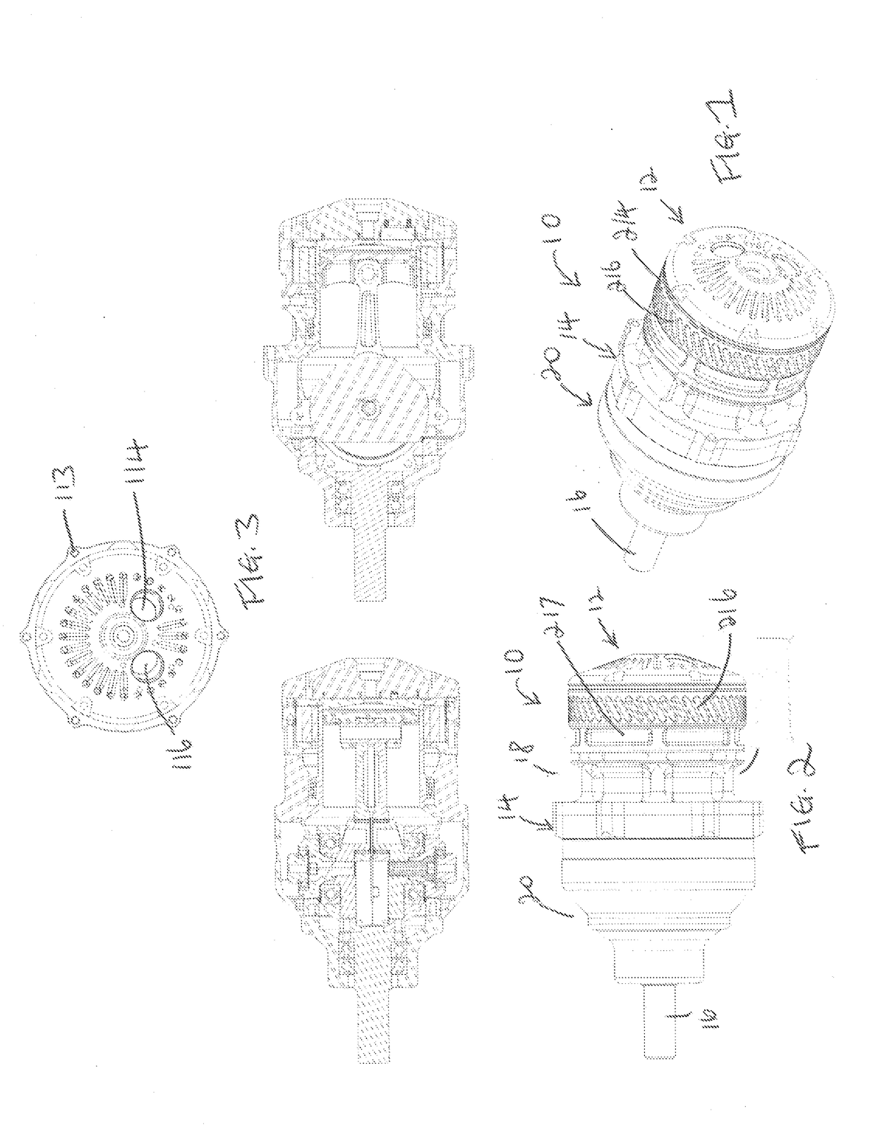
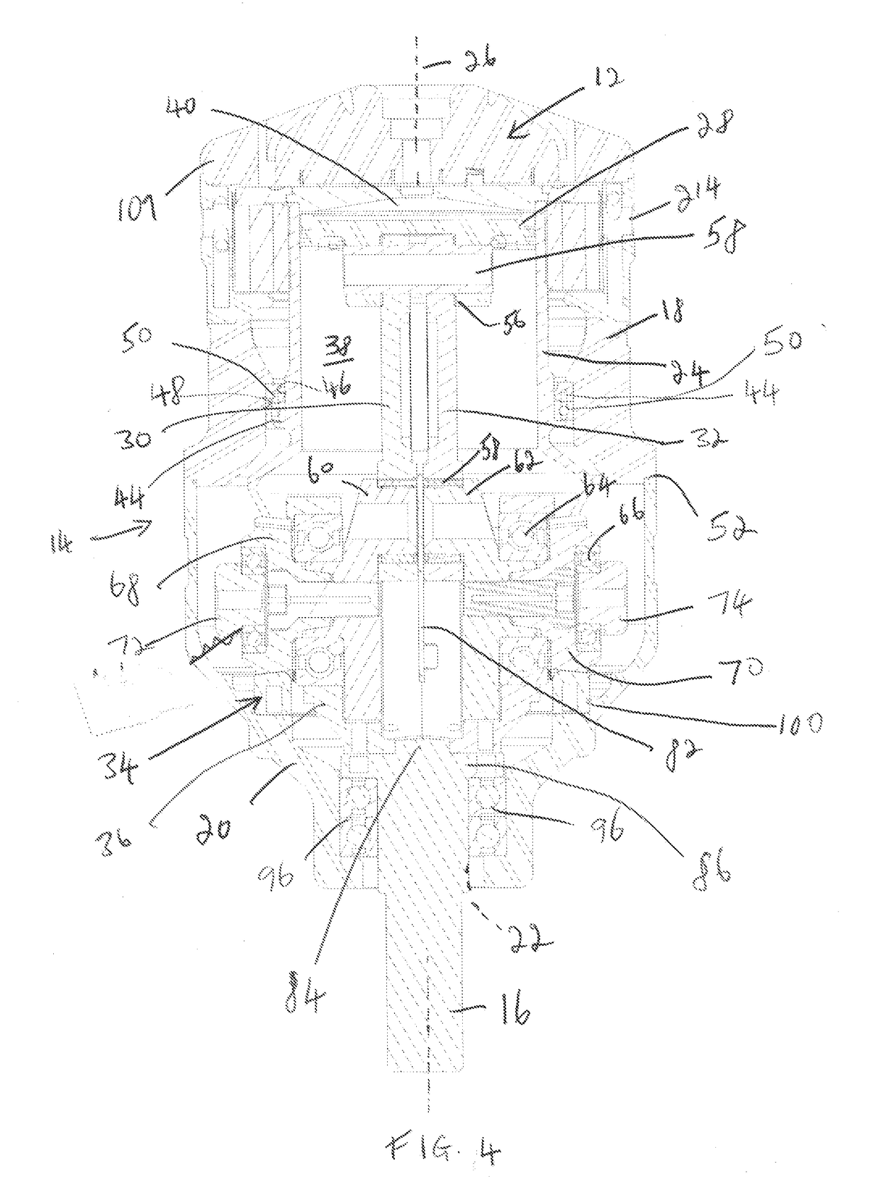
[0125]Referring now to FIGS. 1-11, a balanced rotary engine is shown generally at 10. Broadly speaking, the rotary engine 10 includes a domed cylinder head 12, an outer casing 14, and a drive shaft 16 extending away from the outer casing 14. The outer casing 14 in...


PUM


Abstract

A balanced rotary engine for applying torque to a drive shaft. The engine has an outer casing with a main drive case. A cylinder is rotably mounted in the casing and a piston is mounted to move longitudinally within the cylinder. Two connecting arms, each with a connecting end, one of the ends is connected to the piston, and two crankshafts, each one being rotably connected to the other connecting end of the connecting arms. Two drive wheels are contra-rotably connected to the respective first and second crankshafts. A fixed drive ring has a circumferentially disposed drive member surface. The fixed drive ring is mounted in the case so that the drive member surface faces the piston. The two drive wheels mesh with the drive ring.

Description

TECHNICAL FIELD[0001]The present relates to internal combustion engines, and more particularly to a balanced rotary engine.BACKGROUND[0002]Internal combustion engines with one or more cylinders are well known and widely used in many industries, in particular the automobile industry. Generally speaking, each of the cylinders includes a piston with a spark, or compression, that combusts a hydrocarbon fuel causing explosive power sufficient to reciprocally drive the piston in the cylinder. The power generated by this driven piston can drive a shaft, which when used in traction moves an object, such as a motor vehicle, forwards or rearwards. Also, the power generated can be used statically to move parts in machinery, or can it can generate more power, for example through the use of a generator.[0003]In some cases, this simple mode of operation has been modified such as for example, in the so-called the Wankel engine, which uses one or more specially shaped rotors mounted on a drive shaf...

Claims


Application Information

Patent Timeline
Patent Type & Authority Applications(United States)
IPC IPC(8): F02B75/26F02B75/16F16F15/24
CPCF02B75/26F16F15/24F02B75/16F01B3/0023F02B75/065F01B9/02F02B75/32
Inventor ARSENEAU, MICHEL
Owner QUEBEC ENGINE TECH LLC
Why Eureka
Try Eureka