Nerve cuff electrodes fabricated using over-molded lcp

a nerve cuff electrode and over-molded technology, applied in the field of implantable nerve cuff electrodes, can solve the problems of increasing the final cost of the finished product, time and labor, and the method of making these nerve cuff electrodes is typically time-consuming and labor-intensiv

a nerve cuff electrode and over-molded technology, applied in the field of implantable nerve cuff electrodes, can solve the problems of increasing the final cost of the finished product, time and labor, and the method of making these nerve cuff electrodes is typically time-consuming and labor-intensiv

US20180117313A1Inactive Publication Date: 2018-05-03ALFRED E MANN FOUND FOR SCI RES

Image

  • Nerve cuff electrodes fabricated using over-molded lcp
  • Nerve cuff electrodes fabricated using over-molded lcp
  • Nerve cuff electrodes fabricated using over-molded lcp

Examples


Embodiment Construction

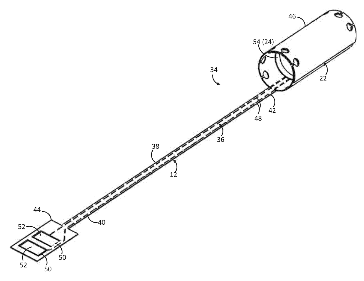
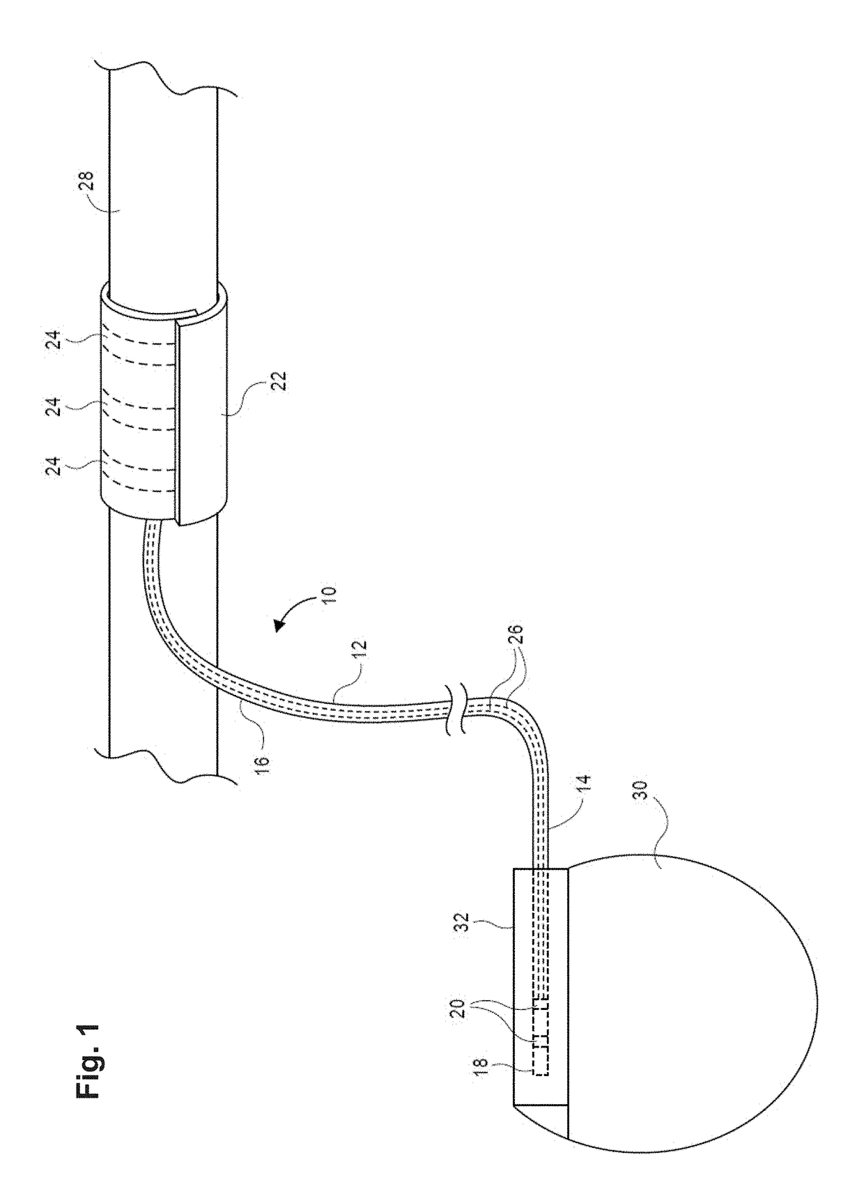
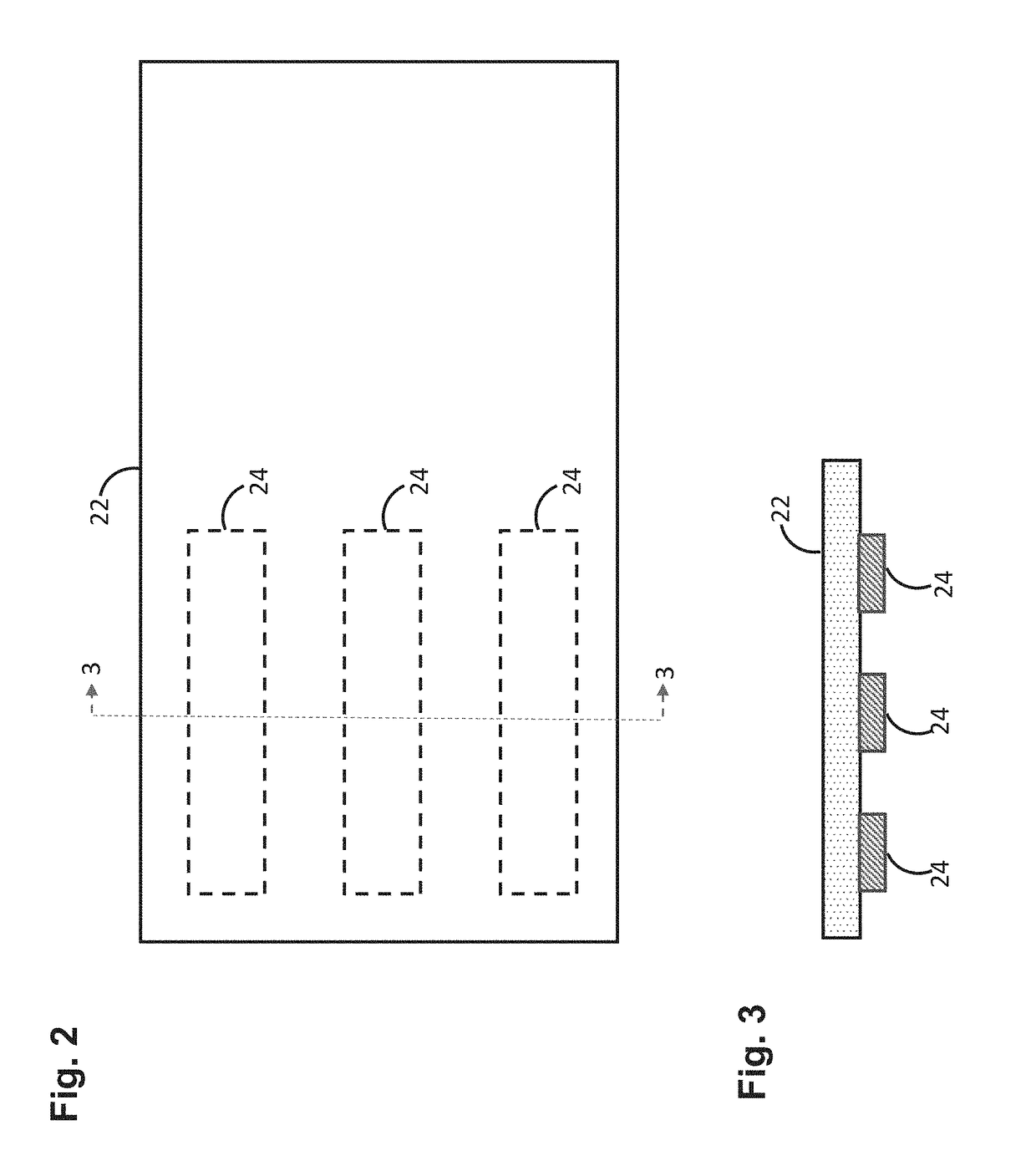
[0078]Referring first to FIGS. 1-3, an electrode lead 10 constructed in accordance with one embodiment of the present inventions will now be described. The electrode lead 10 may be used for any medical treatment where it is desired to stimulate a nerve and / or record physiological signals from a nerve or surrounding tissue.

[0079]The electrode lead 10 generally comprises an elongated planar lead body 12 having a proximal end 14 and a distal end 16, a lead connector 18 affixed to the proximal end 14 of the lead body 12, at least one lead connector contact 20 (two shown) disposed on the lead connector 18, a planar electrode carrying structure 22 affixed to the distal end 16 of the lead body 12, at least one electrode contact 24 (three shown in phantom in FIG. 1) disposed on the electrode carrying structure 22, and at least one electrical conductor 26 (two shown) extending through the lead body 12 between the lead connector contacts 20 and the electrode contacts 24. For the purposes of t...


PUM


Abstract

An electrode lead may comprise a flexible circuit that includes a planar dielectric substrate including an elongated lead substrate portion having opposing ends, an electrode carrying substrate portion disposed on one end of the lead substrate portion, and a connector substrate portion disposed on the other end of the lead substrate portion, wherein the lead substrate portion is pre-shaped into a three-dimensional structure. The flexible circuit may further include an electrically conductive trace extending from the connector substrate portion to the electrode carrying substrate portion, a first window formed in the connector substrate portion to expose the electrically conductive trace to form a connector pad, and a second window formed in the electrode carrying substrate portion to expose the electrically conductive trace to form an electrode pad. The electrode lead may further comprise a lead connector that incorporates the connector substrate portion.

Description

RELATED APPLICATION[0001]This application is a continuation of co-pending U.S. Provisional Patent Application Ser. No. 62 / 415,028, filed Oct. 31, 2016, which is expressly incorporated herein by reference.FIELD OF THE INVENTION[0002]The present invention generally relates to implantable neurostimulation leads, and specifically relates to implantable nerve cuff electrodes that can be used to stimulate nerves.BACKGROUND OF THE INVENTION[0003]Nerve cuff electrodes are conventionally manufactured using implantable grade silicone or, in some cases, polyurethane. Nerve cuff electrodes generally comprise a lead body, a connector proximally located on the lead body, a cuff body distally located on the lead body, electrode contacts placed on the inner surface of the cuff body, and electrical conductors extending from the cuff body through the lead body to the connector. The method of making these nerve cuffs electrodes is typically time consuming, since the conductors and electrode contacts i...

Claims


Application Information

Patent Timeline
03 May 2018
Publication
US20180117313A1
IPC
A61N1/05
CPC
A61N1/0556; A61N1/375; A61N1/0558; A61N1/3605; A61B5/389; A61N1/3752
Inventors
SCHMIDT, SIEGMAR; NG, BOON KHAI