Overhead console and vehicle-body upper structure

Active Publication Date: 2018-05-03
TOYOTA JIDOSHA KK
View PDF5 Cites 4 Cited by
  • Summary
  • Abstract
  • Description
  • Claims
  • Application Information

AI Technical Summary

Benefits of technology

[0009]In this regard, the light guiding member provided in the above overhead console is formed in a shape extending with the bending portions provided at intermediate positions in thereof. Further, the light guiding member has such a shape that line segments that can be drawn between given points on the light incident surface and given points on the light exit surface do not include a line segment that passes through only the light guiding member, that is, a shape in which an optical path that linearly connects the light incident surface to the light exit surface cannot be formed thereinside. In such a light guiding member, the light incident on the light incident surface reaches the light exit surface through a path bending along the shape of the light guiding member. Accordingly, even inside the flat overhead console, the light guiding member having a sufficiently long optical path formed therein from the light incident surface to the light exit surface can be provided. Further, in such a case, even if the light exit surface is not configured such that the light exit surface is h

Problems solved by technology

In such a case, a deep recess is formed on the design surface of the overhead console, so that its design property decreases.
However, in a case where the light guiding member has a straight shape without a bending portion, the light guiding member with a length sufficient enough to form a sufficiently long optical path may not be provided inside a flat overhead console.
That is, if the partition wall is provided, the leak light from the light source is blocked by the partition wall, so that the leak light cannot reach the light exit surface directly.
Note that it might be difficult that the entire light exit surface is irradiated with light with

Method used


Image

  • Overhead console and vehicle-body upper structure
  • Overhead console and vehicle-body upper structure
  • Overhead console and vehicle-body upper structure

Examples


Embodiment Construction

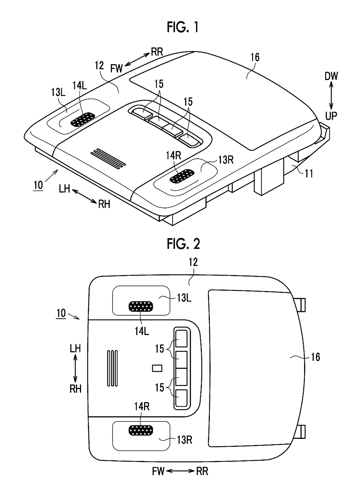
[0041]The following description describes one embodiment of an overhead console and a vehicle-body upper structure in detail with reference to FIGS. 1 to 14. Note that, in each figure to be referred to in the following description, in the vehicle-body upper structure or the overhead console assembled to the vehicle-body upper structure, a direction toward a vehicle-body front side is indicated by an arrow FW, a direction toward a vehicle-body rear side is indicated by an arrow RR, a direction toward a vehicle-body left side is indicated by an arrow LH, a direction toward a vehicle-body right side is indicated by an arrow RH, a direction toward a vehicle-body upper side is indicated by an arrow UP, and a direction toward a vehicle-body lower side is indicated by an arrow DW. Further, in the following description, in a state where the overhead console is assembled to the vehicle-body upper structure, the vehicle-body front side, the vehicle-body rear side, the vehicle-body left side, ...


PUM


Abstract

An overhead console includes: a light source; and a light guiding member including bending portions at intermediate positions in the light guiding member such that the light guiding member extends from the light incident surface to the light exit surface so as to form an optical path in which light incident on the light incident surface is reflected by reflecting surfaces provided in the bending portions so as to reach the light exit surface, the light guiding member having such a shape that line segments drawn between given points on the light incident surface and given points on the light exit surface do not include a line segment that passes through only the light guiding member.

Description

INCORPORATION BY REFERENCE[0001]The disclosure of Japanese Patent Application No. 2016-215423 filed on Nov. 2, 2016 including the specification, drawings and abstract is incorporated herein by reference in its entirety.BACKGROUND1. Technical Field[0002]The present disclosure relates to an overhead console and a vehicle-body upper structure provided with the overhead console.2. Description of Related Art[0003]As an overhead console assembled to a ceiling part of a passenger compartment of an automobile, there is an overhead console including a map lamp throwing light on a hand part of an occupant sitting on a front seat. Conventionally, as the overhead console equipped with the map lamp, one described in Japanese Patent Application Publication No. 2010-132047 (JP 2010-132047 A) has been known.[0004]FIG. 16 illustrates a structure of a map lamp of an overhead console described in JP 2010-132047 A. As illustrated in the figure, the overhead console described in JP 2010-132047 A is conf...

Claims


Application Information

Patent Timeline
IPC IPC(8): B60Q3/66B60Q3/76B60Q3/72
CPCB60Q3/66B60Q3/76B60Q3/72B60Q3/64B60Q3/208B60Q3/54B60Q3/51B60Q3/62F21V7/00F21W2106/00F21S43/249F21S43/243
Inventor SATO, HARUKO
Owner TOYOTA JIDOSHA KK
Why Eureka
Try Eureka