
Digital frequency measuring apparatus

a digital frequency and measuring device technology, applied in the direction of electrical devices, pulse technique, frequency to pulse train conversion, etc., can solve the problems of reducing the sampling rate, and simultaneously providing relatively high frequency resolution and relatively high sampling ra

Active Publication Date: 2018-05-03
SAMSUNG ELECTRO MECHANICS CO LTD
View PDF0 Cites 19 Cited by
  • Summary
  • Abstract
  • Description
  • Claims
  • Application Information

AI Technical Summary

Benefits of technology

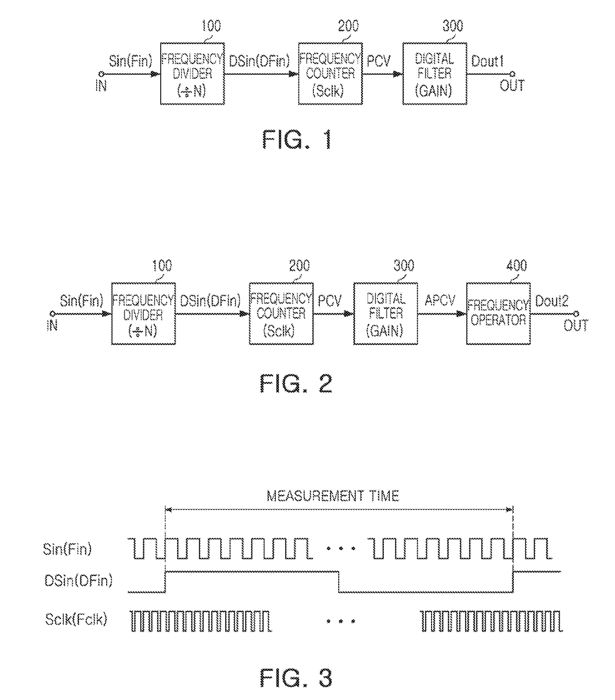
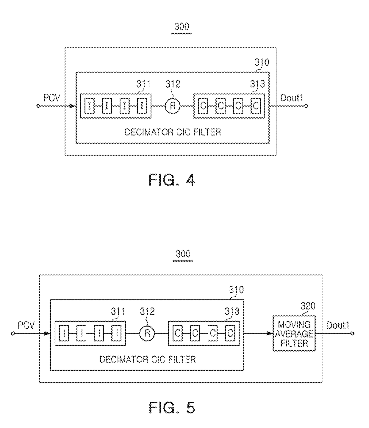
The patent describes a digital frequency measuring apparatus that includes a frequency divider, a period counter, a digital filter, and a frequency operator. The digital filter amplifies the period count value using an accumulated gain determined by a predetermined stage number and a predetermined decimator factor. The digital filter may include a decimator cascaded integrator (CIC) filter and a moving average filter. The frequency operator converts the amplified period count value into an output frequency. The technical effect of this invention is to provide a more accurate and efficient method for measuring the frequency of a signal.

Problems solved by technology

Various frequency measuring methods are commonly used in the related art, but there may be difficulties in simultaneously providing relatively high frequency resolution as well as a relatively high sampling rate.
However, as sampling rate increases, frequency resolution degrades.
On the other hand, when frequency resolution is increased, the time it takes to measure the frequency increases, thereby degrading the sampling rate.
However, using an oscillator with a high frequency in order to increase the resolution of the measured input frequency, decreases the sampling rate.
In conventional frequency measuring techniques, when an input frequency is similar to or greater than that of a main oscillator, discrimination of frequencies becomes difficult.
As described above, in a case in which frequency measuring methods of the related art are used, satisfying both frequency resolution and sampling rate in a trade-off relationship may be problematic.

Method used


Image

  • Digital frequency measuring apparatus
  • Digital frequency measuring apparatus
  • Digital frequency measuring apparatus

Examples


Embodiment Construction

[0050]The following detailed description is provided to assist the reader in gaining a comprehensive understanding of the methods, apparatuses, and / or systems described herein. However, various changes, modifications, and equivalents of the methods, apparatuses, and / or systems described herein will be apparent to one of ordinary skill in the art. The sequences of operations described herein are merely examples, and are not limited to those set forth herein, but may be changed as will be apparent to one of ordinary skill in the art, with the exception of operations necessarily occurring in a certain order. Also, descriptions of functions and constructions that are well known to one of ordinary skill in the art may be omitted for increased clarity and conciseness.

[0051]The features described herein may be embodied in different forms, and are not to be construed as being limited to the examples described herein. Rather, the examples described herein have been provided so that this disc...


PUM


Abstract

A digital frequency measuring apparatus includes a frequency divider dividing an input frequency signal and providing a divided frequency signal; a period counter counting clock cycles in a period of the divided frequency signal using a clock signal and providing a period count value for each period; and a digital filter amplifying the period count value using an accumulated gain, converting an amplified period count value into a frequency, and providing a first digital output value. The digital filter determines the accumulated gain using a predetermined stage number and a predetermined decimator factor.

Description

CROSS-REFERENCE TO RELATED APPLICATION[0001]This application claims the benefit under 35 USC 119(a) of Korean Patent Application Nos. 10-2016-0141902 filed on Oct. 28, 2016 and 10-2016-0175036 filed on Dec. 20, 2016 in the Korean Intellectual Property Office, the entire disclosure of which is incorporated herein by reference for all purposes.BACKGROUND[0002]1. Field[0003]The following description relates to a digital frequency measuring apparatus.[0004]2. Description of Related Art[0005]Various frequency measuring methods are commonly used in the related art, but there may be difficulties in simultaneously providing relatively high frequency resolution as well as a relatively high sampling rate.[0006]In detail, in terms of relatively high frequency resolution in measuring frequencies, precise control and discrimination are possible. When measuring impedance (magnitude and phase) between nodes, using a relatively high frequency resolution results in a more accurate measurement. When ...

Claims


Application Information

Patent Timeline
IPC IPC(8): G01R23/02H03K21/10H03K21/40H03H17/06
CPCG01R23/02H03H17/0671H03K21/40H03K21/10G01R23/10
Inventor LEE, JONG WOOLEE, JOO HYOUNGRYU, JE HYUKCHOI, WOO YOUNGJI, YONG WOONLEE, SOO WOONGHONG, BYUNG JOOKO, JOO YUL
Owner SAMSUNG ELECTRO MECHANICS CO LTD
Learn More