
Cell frame for accommodating pouch cells

a cell frame and pouch technology, applied in the field of cell frames, can solve the problems of additional components needed to make electrical contact with the battery cells, production and material costs in electrical energy stores, and the need to accept lower power density, so as to reduce the number of individual parts for producing the battery pack, good access to the contact pads, and freedom of cell connector isolation

Inactive Publication Date: 2018-05-03
ROBERT BOSCH GMBH
View PDF1 Cites 0 Cited by
  • Summary
  • Abstract
  • Description
  • Claims
  • Application Information

AI Technical Summary

Benefits of technology

The patent text describes a battery pack with a cell frame and foil sleeve made of soft and flexible materials. The cell frame is integrated with the cell connector, reducing the number of individual parts. The foil sleeve can store both primary and secondary battery cells, providing flexibility in energy storage. The use of a foil sleeve with low thickness and a simple joining process allows for space-saving solutions. The battery pack contains two mirror-symmetrical variants of pouch cells, further optimizing space usage. The provision of the cell frame with integrated cell connector simplifies the production process and improves accessibility for tools.

Problems solved by technology

The production and material costs in electrical energy stores likewise represent a challenge.
As a result, although the requirements on energy content and costs are achieved, a lower power density has to be accepted for this purpose.
The disadvantage with this solution is that additional components are needed to make electrical contact with the battery cells.

Method used


Image

  • Cell frame for accommodating pouch cells
  • Cell frame for accommodating pouch cells
  • Cell frame for accommodating pouch cells

Examples


Embodiment Construction

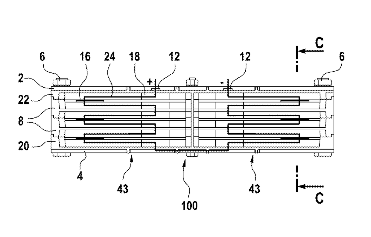
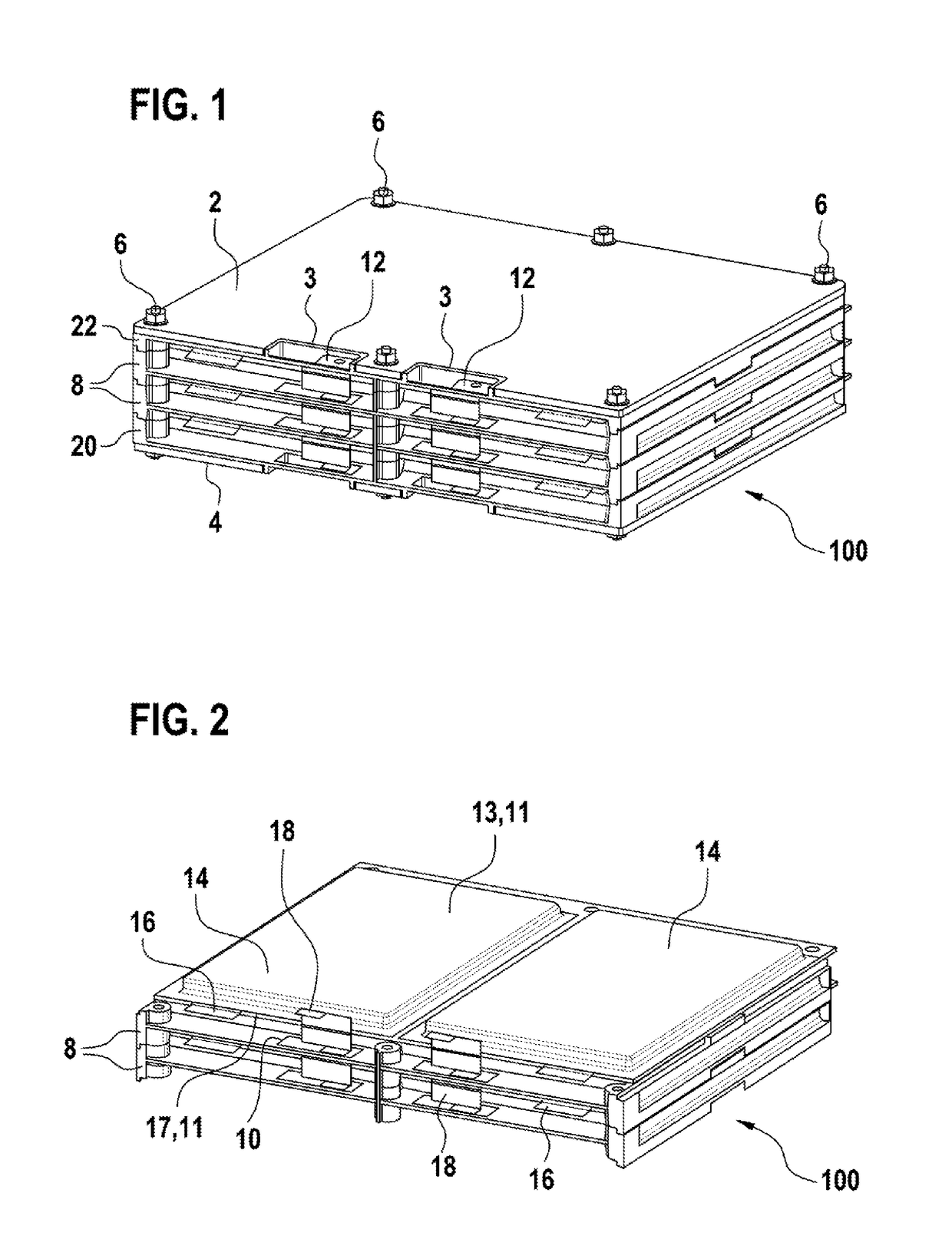
[0050]FIG. 1 shows a perspective view of a framework 100 according to an embodiment of the invention. The framework 100 can form part of a battery pack.

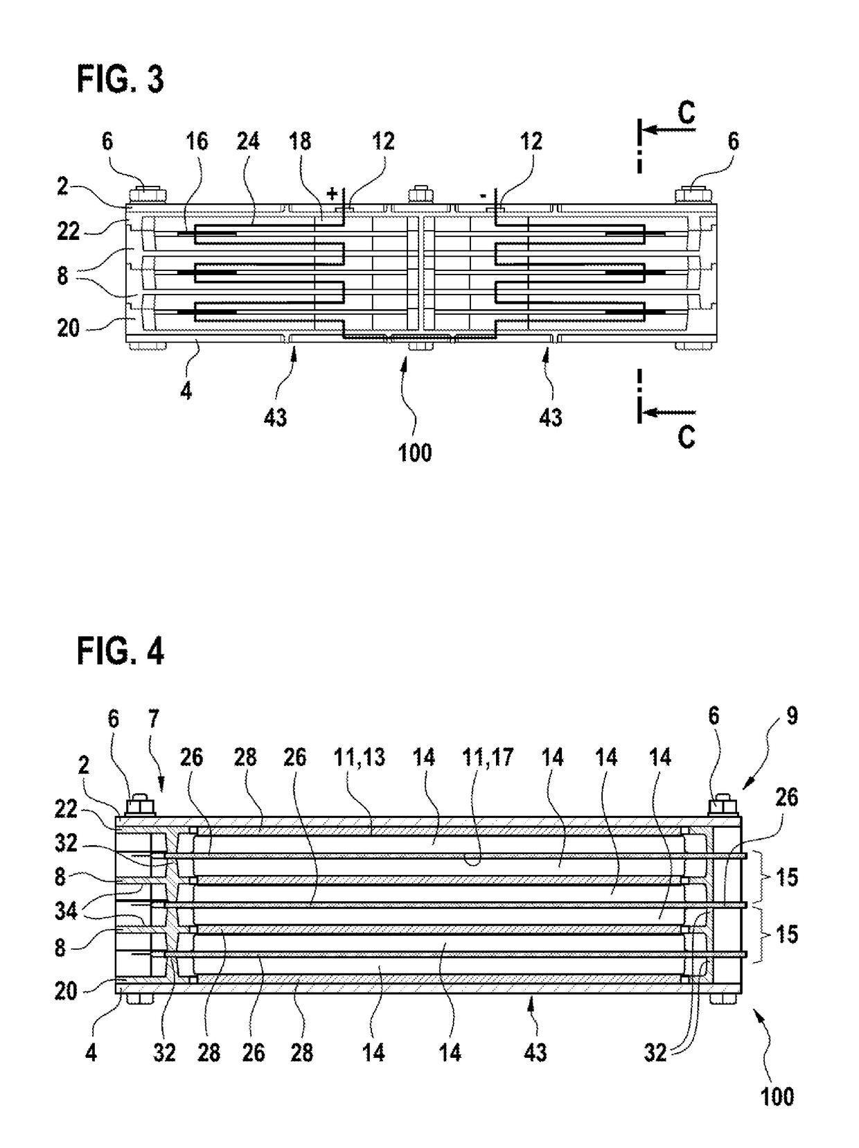
[0051]The framework 100 comprises an arrangement having a top plate 2, an end frame 22, two cell frames 8, a start frame 20 and a bottom plate 4 which, in the exemplary embodiment illustrated, are held firmly together in this order by six clamping screws 6. In the exemplary embodiment illustrated, twelve pouch cells 14, which are not visible in this perspective view, are accommodated in the framework 100.

[0052]The top plate 2 has two cut-outs 3 on the front in order to provide connections 12 for making external contact with the pouch cells 14.

[0053]FIG. 2 shows an inverted view of a framework 100 which comprises two cell frames 8 arranged above each other, and eight pouch cells 14 held in the framework 100. The cell frames 8 illustrated are each populated with four pouch cells 14 and constitute part of the framework 100.

[0054]Each po...


PUM

PropertyMeasurementUnit
thicknessaaaaaaaaaa
thicknessaaaaaaaaaa
thicknessaaaaaaaaaa

Abstract

A cell frame (8) for accommodating a specific number of pouch cells (14), having an integrated cell collector (10), wherein the cell connector (10) provides contact pads for clinching. A battery pack and a method for producing a battery pack are also specified.

Description

BACKGROUND OF THE INVENTION[0001]The invention relates to a cell frame for accommodating a specific number of pouch cells. A battery pack and a method for producing a battery pack are also specified.[0002]Battery packs and battery modules for lithium ion pouch cells with different voltage ranges are known. In addition to a highest possible power to weight ratio, in practice strict requirements are placed on the reliability of such energy stores. The production and material costs in electrical energy stores likewise represent a challenge. Therefore, in most systems which are currently used in electric and hybrid vehicles, round cells are still used. As a result, although the requirements on energy content and costs are achieved, a lower power density has to be accepted for this purpose.[0003]US 2011 / 0210954 A1 discloses accommodating battery cells of the “jelly roll” type firstly in a metal pouch and then in a cell frame. The cell frame has a compartment for a rail, in which cell con...

Claims


Application Information

Patent Timeline
Patent Type & Authority Applications(United States)
IPC IPC(8): H01M2/20H01M2/10H01M10/0525H01M10/48H01M50/211H01M50/291H01M50/503H01M50/51H01M50/528
CPCH01M2/206H01M2/1077H01M10/0525H01M10/482H01M10/486H01M2220/20H01M50/528H01M50/291H01M50/51H01M50/211H01M50/503Y02E60/10
Inventor RANNER, JOSEFBADER, MAXIMILIAN OSCARMOSER, MICHAEL
Owner ROBERT BOSCH GMBH
Learn More