Front-end module
a technology of front-end modules and switching devices, which is applied in the direction of transmission, electrical equipment, multiple-port networks, etc., can solve the problems that the configuration of the switching devices of the related art described above is not adequate to ensure isolation, and achieve excellent isolation characteristics
- Summary
- Abstract
- Description
- Claims
- Application Information
AI Technical Summary
Benefits of technology
Problems solved by technology
Method used
Image

Examples
embodiment 1
Preferred Embodiment 1
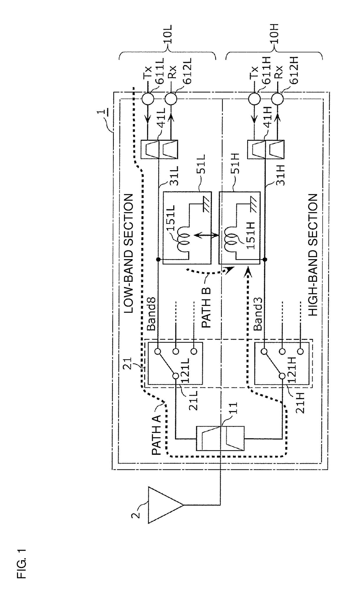
[0042]FIG. 1 is a circuit configuration diagram of a front-end module 1 according to preferred embodiment 1. In the figure, the front-end module 1 according to preferred embodiment 1 and an antenna element 2 are illustrated. The front-end module 1 and the antenna element 2 are preferably provided in the front end of a cellular phone that supports multiple modes / multiple bands, for example.
[0043]The front-end module 1 includes a diplexer 11, an antenna switch module 21, a signal path 31H that is preferably used to propagate signals of Band 3 of the LTE standard (transmission band: 1710-1785 MHz, reception band: 1805-1880 MHz), for example, a signal path 31L that is preferably used to propagate signals of Band 8 of the LTE standard (transmission band: 880-915 MHz, reception band: 925-960 MHz), for example, a first circuit 51L, a second circuit 51H, and duplexers 41H and 41L.
[0044]The front-end module 1 is a multi-carrier transmission / reception device that is prov...
embodiment 2
Preferred Embodiment 2
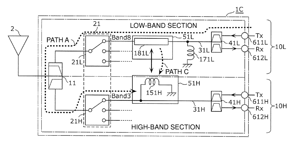
[0091]FIG. 7 is a circuit configuration diagram of a front-end module 1C according to preferred embodiment 2. In FIG. 7, the front-end module 1C according to preferred embodiment 2 and an antenna element 2 are illustrated. The front-end module 1C according to the present preferred embodiment differs from the front-end module 1 according to preferred embodiment 1 only in terms of the circuit configuration of the first circuit 51L. Hereafter, description of portions of the front-end module 1C according to the present preferred embodiment that are the same or substantially the same as the front-end module 1 according to preferred embodiment 1 is omitted, and the description focuses on the portions that are different.
[0092]The first circuit 51L is connected to the signal path 31L (first signal path) that is used to propagate Band 8 (first frequency band) signals. In addition, the second circuit 51H is connected to the signal path 31H (second signal path) that is us...
embodiment 3
Preferred Embodiment 3
[0110]In preferred embodiment 3, a front-end module 1D is described that is obtained by adding, to a configuration in which the isolation characteristics of a first frequency band and a second frequency band that are subjected to a CA operation are improved as in preferred embodiments 1 and 2, a configuration that improves isolation characteristics inside a third frequency band that is not subjected to a CA operation with the two frequency bands.
[0111]FIG. 9 is a circuit configuration diagram of the front-end module 1D according to preferred embodiment 3. In FIG. 9, the front-end module 1D according to preferred embodiment 3 and an antenna element 2 are illustrated. The front-end module 1D and the antenna element 2 are preferably arranged in the front end of a cellular phone that supports multiple modes / multiple bands, for example.
[0112]The front-end module 1D includes the diplexer 11, the antenna switch module 21, the signal path 31H (second signal path) that ...
PUM
 Abstract
Description
Claims
Application Information
 - R&D
- Intellectual Property
- Life Sciences
- Materials
- Tech Scout
- Unparalleled Data Quality
- Higher Quality Content
- 60% Fewer Hallucinations
Browse by: Latest US Patents, China's latest patents, Technical Efficacy Thesaurus, Application Domain, Technology Topic, Popular Technical Reports.
© 2025 PatSnap. All rights reserved.Legal|Privacy policy|Modern Slavery Act Transparency Statement|Sitemap|About US| Contact US: help@patsnap.com