
Liquid ejection device

Active Publication Date: 2018-05-10
SEIKO EPSON CORP
View PDF6 Cites 24 Cited by
  • Summary
  • Abstract
  • Description
  • Claims
  • Application Information

AI Technical Summary

Benefits of technology

The invention is about a liquid ejection device that reduces the risk of its parts coming into contact with the liquid supply container when refilling the device. This is done while keeping the device's size compact.

Problems solved by technology

Here, if refilling of a liquid to the liquid container portion is started in a state in which the opening and closing body is opened, for example, there is a risk of the opening and closing body being unintentionally closed while the refilling of liquid is performed, and the opening and closing body coming into contact with a liquid supply container that is attached to the liquid container portion.

Method used


Image

  • Liquid ejection device
  • Liquid ejection device
  • Liquid ejection device

Examples


working example 1

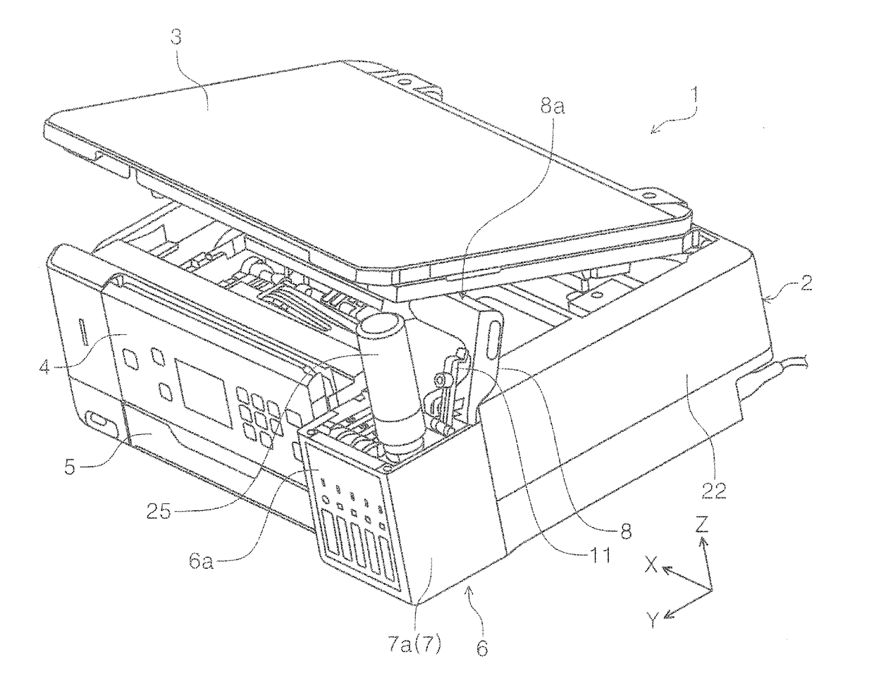
[0051]First, an overview of an inkjet printer 1 (hereinafter, simply referred as printer 1), which is an example of a “liquid ejection device” according to the invention, will be described.

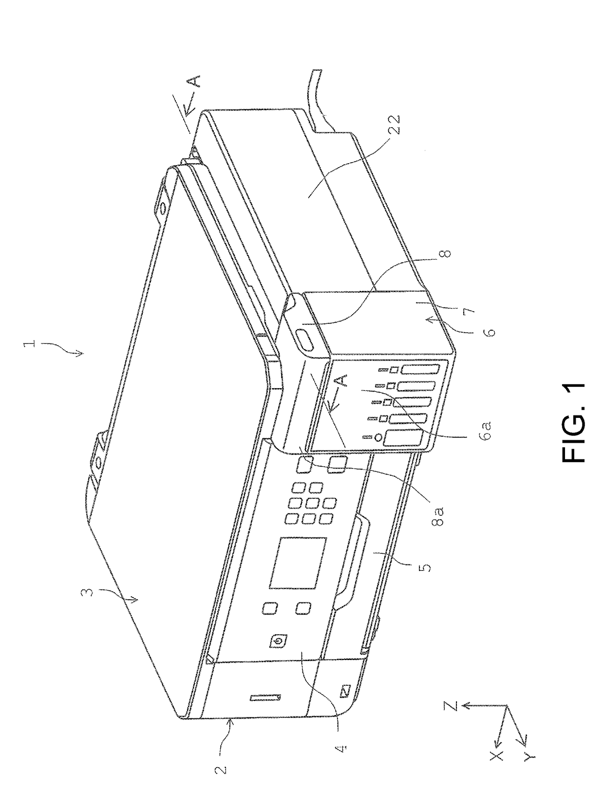
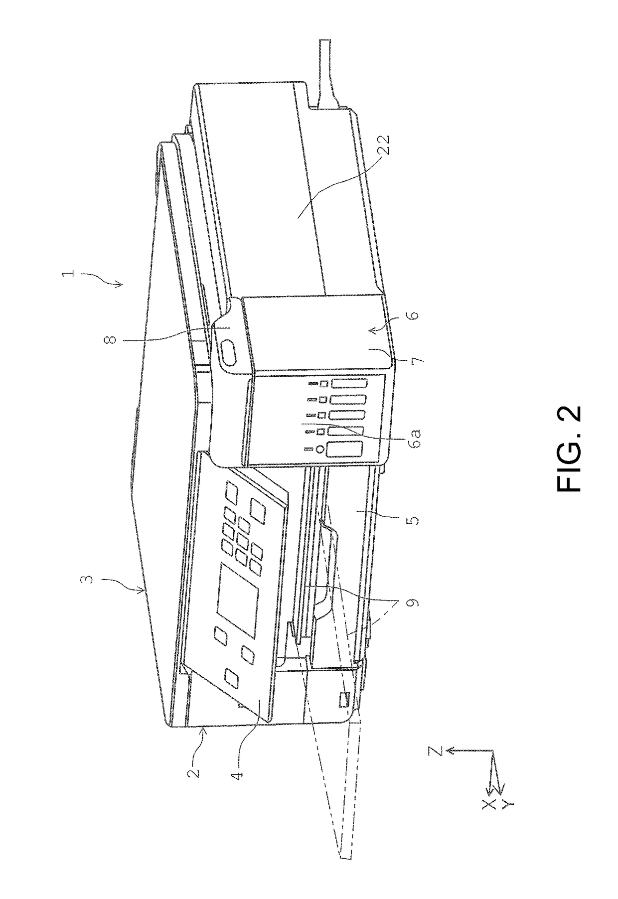
[0052]FIG. 1 is an external perspective view of a printer according to the invention. FIG. 2 is an external perspective view of the printer in a state in which an operation panel is pivoted on a device front surface side. FIG. 3 is an external perspective view of the printer when a scanner and an ink tank cover are in an open state relative to a device body. FIG. 4 is a perspective view illustrating a configuration of the device body. FIG. 5 is a diagram illustrating a state in which a first casing and the ink tank cover of an ink tank portion are removed from the device body. FIG. 6 is an enlarged view of the main portion inside the device body. FIG. 7 is a diagram illustrating a state in which a liquid supply container is attached to an ink injection port in the printer according to the inventio...


PUM


Abstract

A printer 1 serving as a liquid ejection device includes: a device body 2 including a recording head 20 that ejects ink; a scanner unit 3 that closes and opens at least a portion of an upper portion of the device body 2; and a plurality of ink tank 10 that are provided in the device body 2, each contain ink to be supplied to the recording head 20, and each include an ink injection port 26 through which the ink can be injected from a liquid supply container. At least one of the plurality of ink injection ports 26 is located inside an opening and closing region that is opened and closed by the scanner unit 3, and the other ink injection ports 26 are located outside the opening and closing region.

Description

[0001]The present application claims priority from Japanese Patent Application No. 2016-215976 filed on Nov. 4, 2016, the contents of which are hereby incorporated by reference into this application.BACKGROUND1. Technical Field[0002]The present invention relates to a liquid ejection device that ejects a liquid.2. Related Art[0003]Some inkjet printers, which are examples of a liquid ejection device, include a recording head for ejecting ink, which is a liquid, onto a recording medium to perform recording, and a liquid container portion that contains ink that is supplied to the recording head, and the liquid container portion can be refilled with ink that is consumed when recording is performed (JP-A-2016-132165, for example).[0004]A printer unit 11 in a multifunction peripheral 10 described in JP-A-2016-132165 includes, inside a casing 14, an ink tank 100 (corresponding to the liquid container portion) that can be refilled with ink at a position outside a conveyance path 65 (on a rig...

Claims


Application Information

Patent Timeline
IPC IPC(8): B41J2/175
CPCB41J2/17506B41J2/17503B41J2/17509B41J2/17553B41J3/445B41J2/1752B41J29/02B41J29/13
Inventor MORIYAMA, RYUJIAKAHANE, HISAYUKISATO, MAKOTO
Owner SEIKO EPSON CORP
Features
  • Generate Ideas
  • Intellectual Property
  • Life Sciences
  • Materials
  • Tech Scout
  • Unparalleled Data Quality
  • Higher Quality Content
  • 60% Fewer Hallucinations
Learn More