
Non-contact voltage measurement system

a voltage measurement and non-contact technology, applied in the direction of voltage measurement only, instruments, base element modifications, etc., can solve the problems of not providing an indication of actual magnitude, relatively dangerous step of touching voltmeter probes to stripped wires or terminals

Active Publication Date: 2018-05-10
JOHN FLUKE MFG CO INC
View PDF4 Cites 25 Cited by
  • Summary
  • Abstract
  • Description
  • Claims
  • Application Information

AI Technical Summary

Benefits of technology

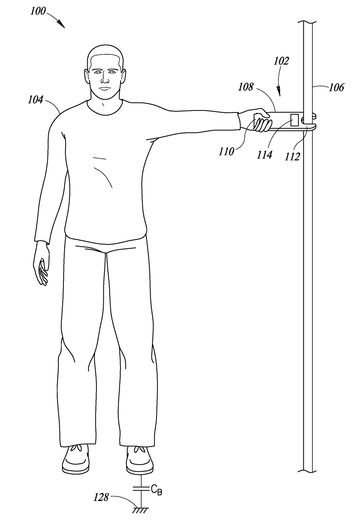
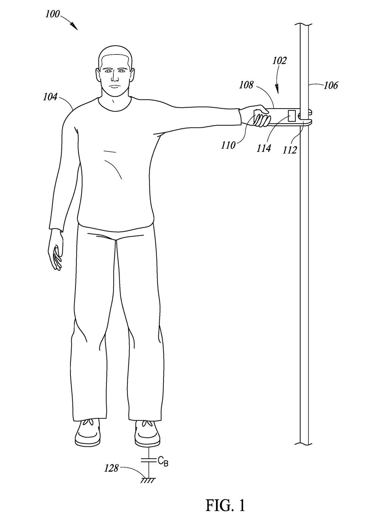
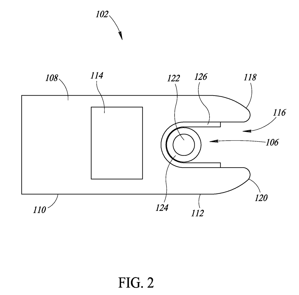
The patent describes a system for measuring alternating current (AC) in an insulated conductor. The system includes a conductive sensor that is placed near the conductor without touching it, a variable capacitance subsystem, and a voltage measurement subsystem. The system measures the voltage across the conductor using the conductive sensor and the voltage measurement subsystem. The system uses a processor to control the voltage across the conductor and to detect the voltage at different locations. The processor uses instructions or data stored in a non-transitory memory to determine the AC voltage in the conductor. The system can provide a user interface to display or light up the results of the AC voltage measurement. The technical effect of the system is to provide a reliable and accurate method for measuring AC voltage in an insulated conductor.

Problems solved by technology

Besides requiring an exposed wire or terminal for galvanic contact, the step of touching voltmeter probes to stripped wires or terminals can be relatively dangerous due to the risks of shock or electrocution.
However, such non-contact voltage detectors provide only an indication of the presence or absence of an AC voltage, and do not provide an indication of the actual magnitude (e.g., RMS value) of the AC voltage.

Method used


Image

  • Non-contact voltage measurement system
  • Non-contact voltage measurement system
  • Non-contact voltage measurement system

Examples


Embodiment Construction

[0020]In the following description, certain specific details are set forth in order to provide a thorough understanding of various disclosed implementations. However, one skilled in the relevant art will recognize that implementations may be practiced without one or more of these specific details, or with other methods, components, materials, etc. In other instances, well-known structures associated with computer systems, server computers, and / or communications networks have not been shown or described in detail to avoid unnecessarily obscuring descriptions of the implementations.

[0021]Unless the context requires otherwise, throughout the specification and claims that follow, the word “comprising” is synonymous with “including,” and is inclusive or open-ended (i.e., does not exclude additional, unrecited elements or method acts).

[0022]Reference throughout this specification to “one implementation” or “an implementation” means that a particular feature, structure or characteristic de...


PUM


Abstract

Systems and methods for measuring alternating current (AC) voltage of an insulated conductor (e.g., insulated wire) are provided, without requiring a galvanic connection between the conductor and a test electrode or probe. A non-galvanic contact (or “non-contact”) voltage measurement system includes a variable capacitance subsystem which operates to generate a variable capacitive voltage between an insulated conductor under test and earth ground. During measurement, the non-contact voltage measurement system varies the capacitance of the variable capacitance subsystem to change the impedance of a capacitive divider circuit between the insulated conductor under test and earth ground. By sequentially making two (or three) measurements across the variable capacitance subsystem, the AC voltage of the insulated conductor can be determined without requiring any galvanic connection to the insulated conductor. The determined AC voltage of the insulated conductor may then be presented to an operator and / or communicated to an external device.

Description

BACKGROUNDTechnical Field[0001]The present disclosure generally relates to measurement of electrical characteristics, and more particularly, to non-contact measurement of alternating current (AC) voltage.Description of the Related Art[0002]Voltmeters are instruments used for measuring voltage in an electric circuit. Instruments which measure more than one electrical characteristic are referred to as multimeters or digital multimeters (DMMs), and operate to measure a number of parameters generally needed for service, troubleshooting, and maintenance applications. Such parameters typically include alternating current (AC) voltage and current, direct current (DC) voltage and current, and resistance or continuity. Other parameters, such as power characteristics, frequency, capacitance, and temperature, may also be measured to meet the requirements of the particular application.[0003]With conventional voltmeters or multimeters which measure AC voltage, it is necessary to bring at least o...

Claims


Application Information

Patent Timeline
IPC IPC(8): G01R15/16G01R19/25
CPCG01R19/2503G01R15/16G01R19/0084G01R1/22G01R15/14G01R15/142G01R19/00
Inventor RINGSRUD, PAUL ANDREWHUBER, CLARK N.GALLAVAN, MICHAEL F.
Owner JOHN FLUKE MFG CO INC
Learn More