
Stylus having variable transmit signal strength, and sensor for detecting such stylus

a technology of transmit signal strength and stylus, which is applied in the direction of instruments, computing, electric digital data processing, etc., can solve the problems of limiting the distance weakening the signal sent or received between the stylus and the electronic device, and saturated receiving circuitry in the device, so as to improve the distance or height

Active Publication Date: 2018-05-10
WACOM CO LTD
View PDF3 Cites 5 Cited by
  • Summary
  • Abstract
  • Description
  • Claims
  • Application Information

AI Technical Summary

Benefits of technology

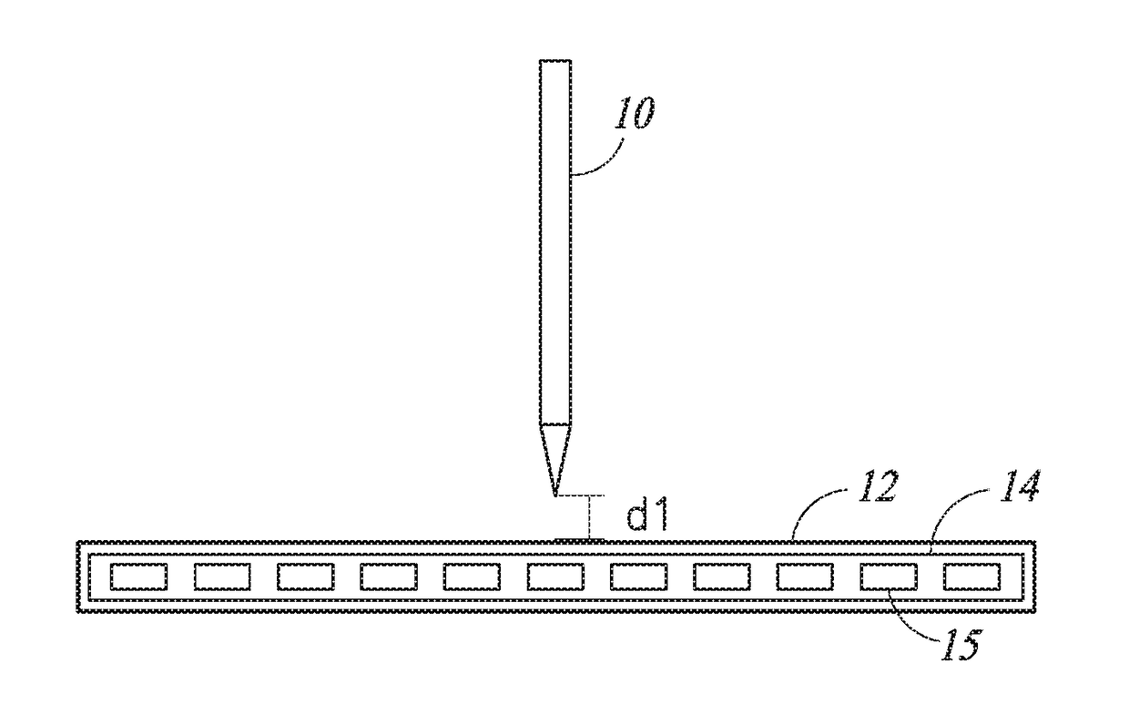
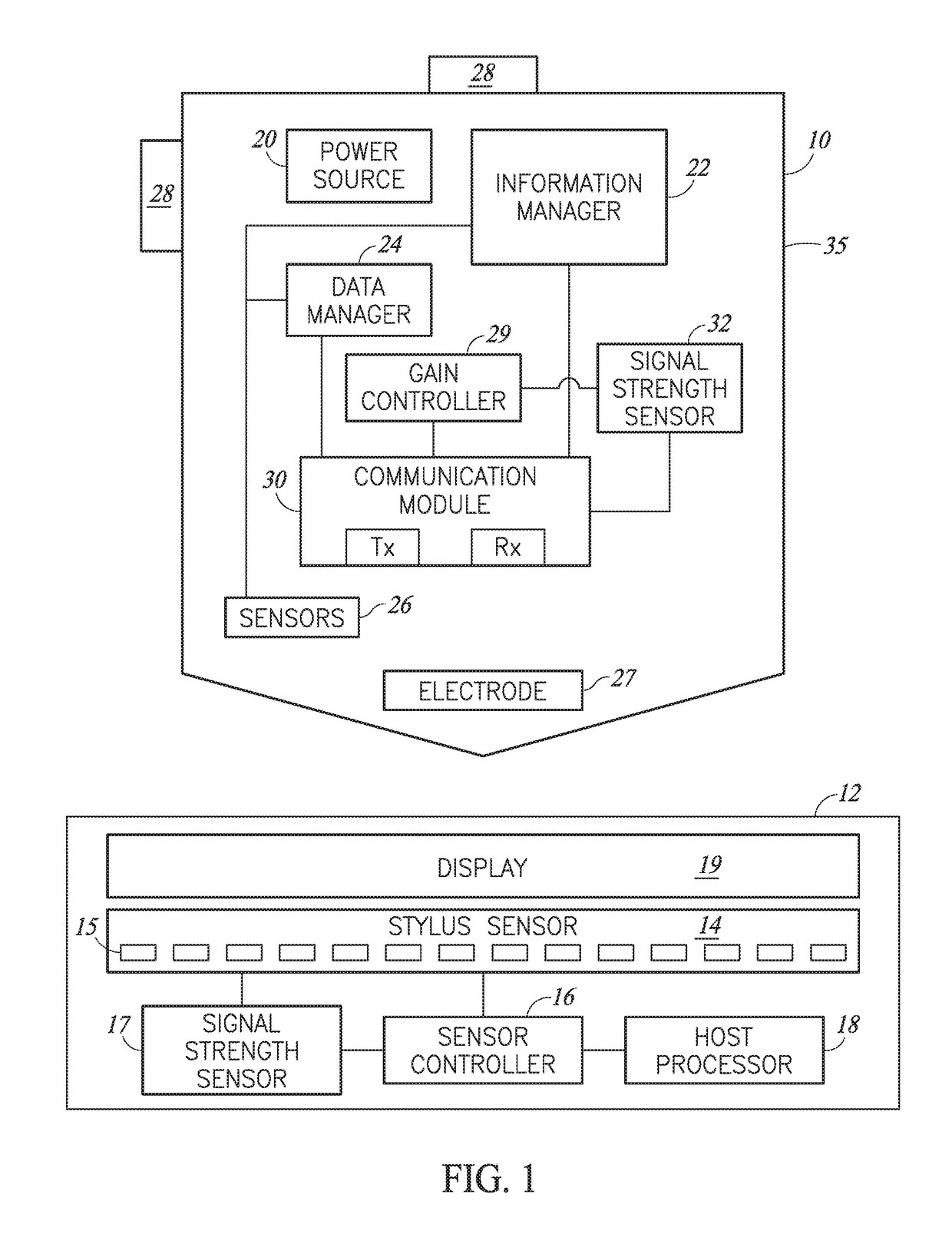
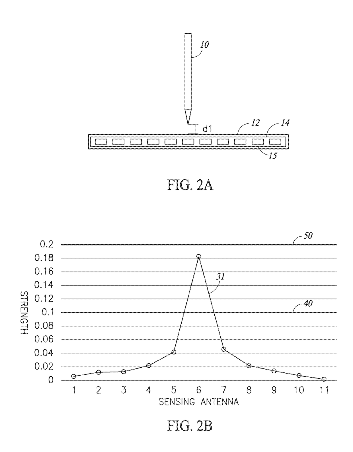
The present patent is about a system and method for improving the detection of a stylus on electronic devices by adjusting the strength of signals transmitted by the stylus based on its distance from the device. By measuring the strength of the signals, the method can determine the height of the stylus relative to the device and adjust the strength of the signal transmitted by the stylus accordingly to increase or decrease its detectable height. This can improve the accuracy of data input from the stylus and conserve power by reducing the strain on the device caused by overloading or saturation of the signal transmitted by the stylus.

Problems solved by technology

Unfortunately, there is a limit as to how far away a stylus may be from an electronic device as signals sent or received between the stylus and the electronic device generally become weaker as the stylus moves further away from the electronic device.
Attempting to overcome this by increasing the signal sent by the stylus often results in the receiving circuitry in the device becoming saturated when the stylus is near the surface.
Accordingly, a stylus and an electronic device are typically unable to communicate unless they are in within close proximity of each other.

Method used


Image

  • Stylus having variable transmit signal strength, and sensor for detecting such stylus
  • Stylus having variable transmit signal strength, and sensor for detecting such stylus
  • Stylus having variable transmit signal strength, and sensor for detecting such stylus

Examples


Embodiment Construction

[0020]In the following description, for purposes of explanation, numerous specific details are set forth in order to provide a thorough understanding of the present invention. It will be evident, however, to one skilled in the art that the present invention may be practiced without these specific details. In other instances, well-known circuits, structures, and techniques are not shown in detail, but rather in a block diagram in order to avoid unnecessarily obscuring an understanding of this description. Thus, the specific details set forth are merely exemplary. Particular implementations may vary from these exemplary details and still be contemplated to be within the scope of the present invention. Reference in the description to “one embodiment” or “an embodiment” means that a particular feature, structure, or characteristic described in connection with the embodiment is included in at least one embodiment of the invention. The phrase “in one embodiment” located in various places ...


PUM


Abstract

Various embodiments provide detection of a stylus at a large distance from a surface of a device, such as a tablet, by increasing the stylus' transmitted signal strength. In addition, signal strength transmitted by the stylus is lowered when the stylus is close to the surface of the device to avoid saturating of a receiving circuit of the device and conserve power. The distance between the stylus and the surface of the device is determined by measuring the strength of a signal received by the stylus and / or a signal received by the device.

Description

BACKGROUNDTechnical Field[0001]This disclosure relates to improving detection of a stylus by an electronic device, such as a tablet based computing device or a tablet peripheral attached to a computing device.Description of the Related Art[0002]Many current styli include various electronic components that facilitate bidirectional communication (i.e., sending and receiving signals) with an electronic device, such as a tablet or mobile phone. For example, an electronic device may send a request for data from a stylus and the stylus may send the requested data. A location of a stylus on a surface of an electronic device may be determined based on a signal transmitted by the stylus. Namely, a control circuit in the electronic device may sequentially sample signals from the active stylus, and the location of the stylus may be determined based on the signal strengths of the sampled signals.[0003]Unfortunately, there is a limit as to how far away a stylus may be from an electronic device a...

Claims


Application Information

Patent Timeline
IPC IPC(8): G06F3/038G06F3/041G06F3/0354
CPCG06F3/0383G06F2203/04108G06F3/03545G06F3/0416G06F2203/04101G06F3/0441G06F3/04162G06F3/0442G06F2203/0384
Inventor FLECK, DAVID CHARLES
Owner WACOM CO LTD
Learn More