Wireless resource allocation device, wireless resource allocation method, and recording medium storing wireless resource allocation program

Active Publication Date: 2018-05-10
NEC CORP
View PDF5 Cites 8 Cited by
  • Summary
  • Abstract
  • Description
  • Claims
  • Application Information

AI Technical Summary

Benefits of technology

The present invention is about a program that helps improve the allocation of wireless resources. It can be stored on a computer-readable recording medium. This invention makes it much more efficient to allocate wireless resources.

Problems solved by technology

But, if the response confirmation is carried out every time the packet is transmitted, there is a problem that the communication rate decreases.

Method used


Image

  • Wireless resource allocation device, wireless resource allocation method, and recording medium storing wireless resource allocation program
  • Wireless resource allocation device, wireless resource allocation method, and recording medium storing wireless resource allocation program
  • Wireless resource allocation device, wireless resource allocation method, and recording medium storing wireless resource allocation program

Examples


first example embodiment

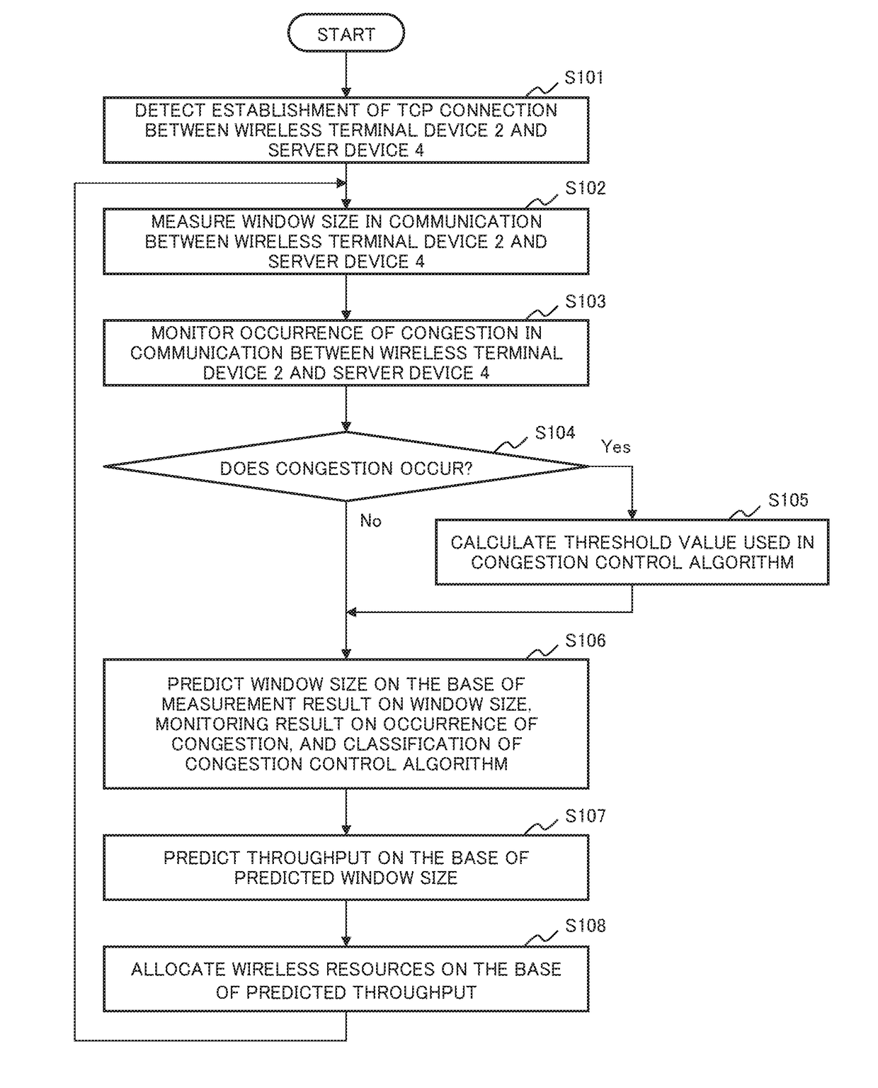
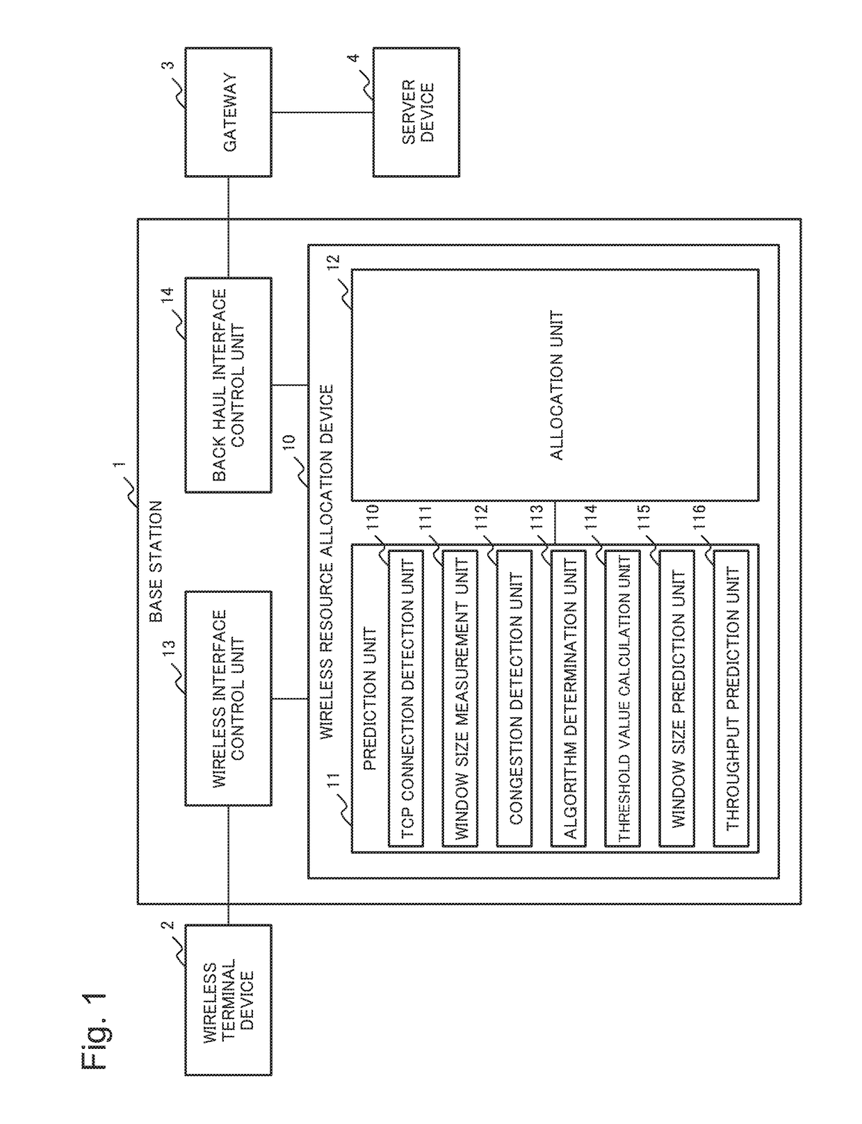
[0024]FIG. 1 is a block diagram conceptually illustrating a configuration of a wireless resource allocation device 10 according to a first example embodiment of the present invention. The wireless resource allocation device 10 is included by a base station 1 which controls a connection of wireless communication with a wireless terminal device 2. The wireless resource allocation device 10 may be another device which is communicably connected with the base station 1.

[0025]The base station 1 includes the wireless resource allocation device 10, a wireless interface control unit 13, and a back haul interface control unit 14. The wireless interface control unit 13 controls transmission and reception of communication data (communication information) which are carried out between the wireless terminal device 2 and the base station 1. The back haul interface control unit 14 controls transmission and reception of communication data which are carried out between the base station 1 and a gatewa...

second example embodiment

[0072]FIG. 9 is a block diagram conceptually illustrating a configuration of a wireless resource allocation device 50 according to a second example embodiment of the present invention.

[0073]The wireless resource allocation device 50 according to the present example embodiment includes a prediction unit 51 and an allocation unit 52.

[0074]The prediction unit 51 predicts a communication rate of communication information, which is transmitted and received by a wireless terminal device 60, on the base that communication-rate-control-information, which is included by the communication information and which is determined by a communication protocol, regularly changes.

[0075]The allocation unit 52 allocates wireless resources, which are used for communication with the wireless terminal device 60, on the base of the communication rate predicted by the prediction unit 51.

[0076]According to the wireless resource allocation device 50 of the present example embodiment, it is possible to improve e...


PUM


Abstract

A wireless resource allocation device 50 includes: a prediction unit 51 that predicts a communication rate of communication information, which is transmitted and received by a wireless terminal device 60, on the base that communication-rate-control-information which is included in the communication information and which is determined by a communication protocol regularly changes; and an allocation unit 52 that allocates wireless resources, which are used for communication with the wireless terminal device 60, on the base of the communication rate predicted by the prediction unit 51.

Description

[0001]This application is based upon and claims the benefit of priority from Japanese Patent Application No. 2016-217748, filed on Nov. 8, 2016, the disclosure of which is incorporated herein in its entirety by reference.TECHNICAL FIELD[0002]The present invention relates to an art to allocate wireless resources which a base station for wireless communication or the like uses for communication with a wireless terminal device.BACKGROUND ART[0003]A base station, which carries out wireless communication connection control to a wireless terminal device such as a smartphone, a tablet terminal, or the like, allocates wireless resources (bandwidth) which are used for wireless communication with each wireless terminal device. Recently, by rapid prevalence of the smartphone and the tablet terminal, data traffic of the wireless communication increases rapidly, and then it is strongly expected to realize an art for the base station's allocating the wireless resources efficiently.[0004]As an art...

Claims


Application Information

Patent Timeline
IPC IPC(8): H04W16/10H04L12/911H04L12/807H04L12/801H04L12/841H04L12/26H04L47/27
CPCH04W16/10H04L47/70H04L47/27H04L47/193H04L47/283H04L43/0864H04W88/08H04L43/0894H04L41/147H04L47/83
Inventor FURUICHI, HIDEYUKI
Owner NEC CORP
Why Eureka
Try Eureka