Digital radio communication system for multi-application

Inactive Publication Date: 2007-06-19
HITACHI LTD
View PDF19 Cites 2 Cited by
  • Summary
  • Abstract
  • Description
  • Claims
  • Application Information

AI Technical Summary

Benefits of technology

[0006]The present invention aims to solve the above-described problem and provide a base station with a means of assigning a radio communication channel preferentially to a mobile station that is requesting an application, such as the above-mentioned ETC system for which a communication should be completed while the mobile station is located in the cell of the base station. In addition, the invention provides the base station with a radio communication channel measuring means. As a result of the measurement performed by this means, if a radio communication channel of poor quality is detected, its throughput is enhanced by re-assigning a plurality of time slots to the mobile station using that channel and encapsulating the same data contents into the plurality of time slots. This technique is applied to reduce the uncompleted communication rate of a communication for such application between a base station and a mobile station located in the cell of the base station.

Problems solved by technology

This system, however, has no arrangement for applications for which the communication between a base station and a mobile station should be completed during the time the mobile station is located in the cell of the base station.
If the radio communication system of MMAC high-speed radio access is applied to an application for which the communication between a base station and a mobile station should be completed while the mobile station is located in the cell of the base station, it is supposed that a radio communication channel satisfying QOS is not assigned to the mobile station, and so it becomes difficult to complete such a communication.

Method used


Image

  • Digital radio communication system for multi-application
  • Digital radio communication system for multi-application
  • Digital radio communication system for multi-application

Examples


Embodiment Construction

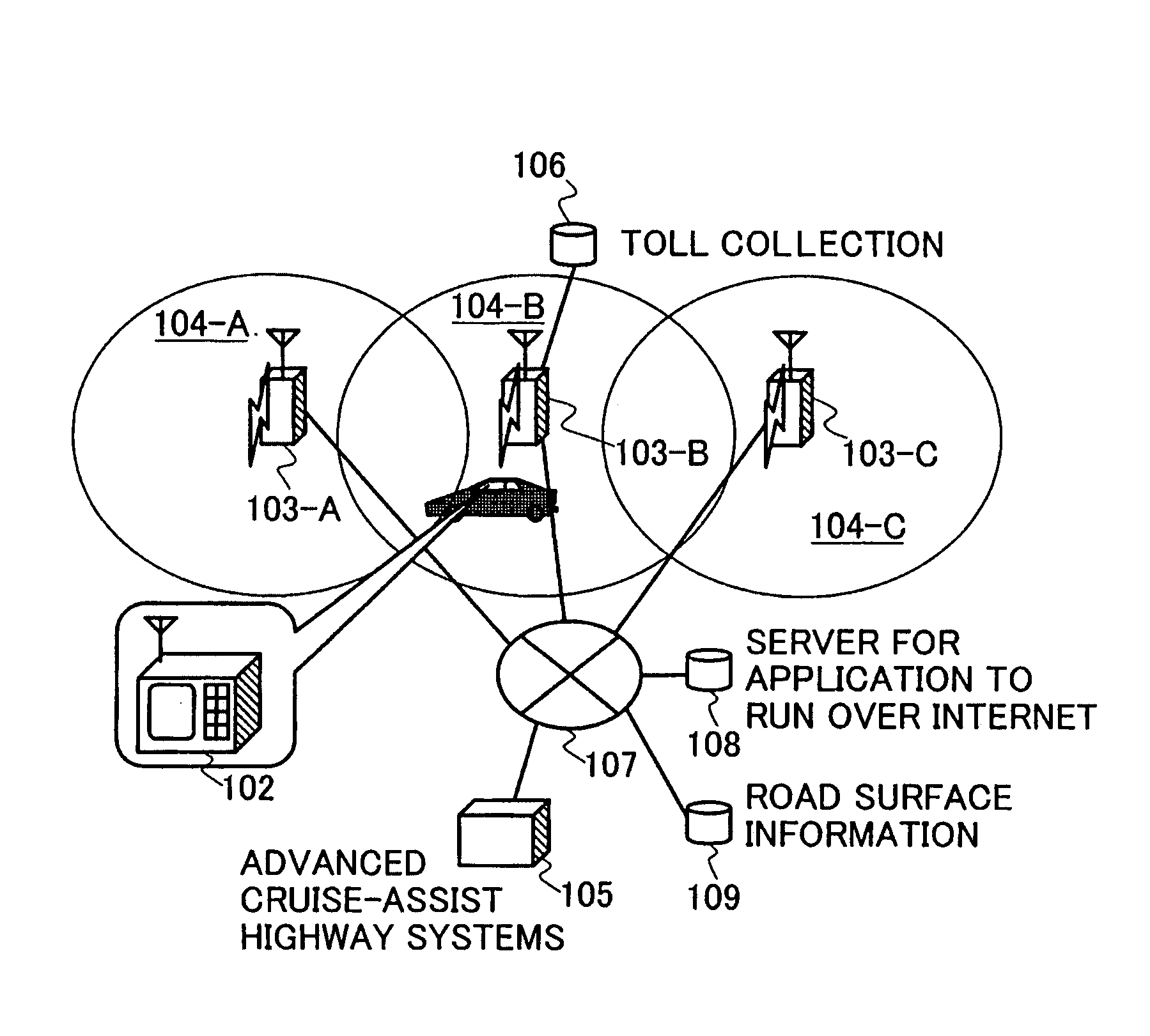
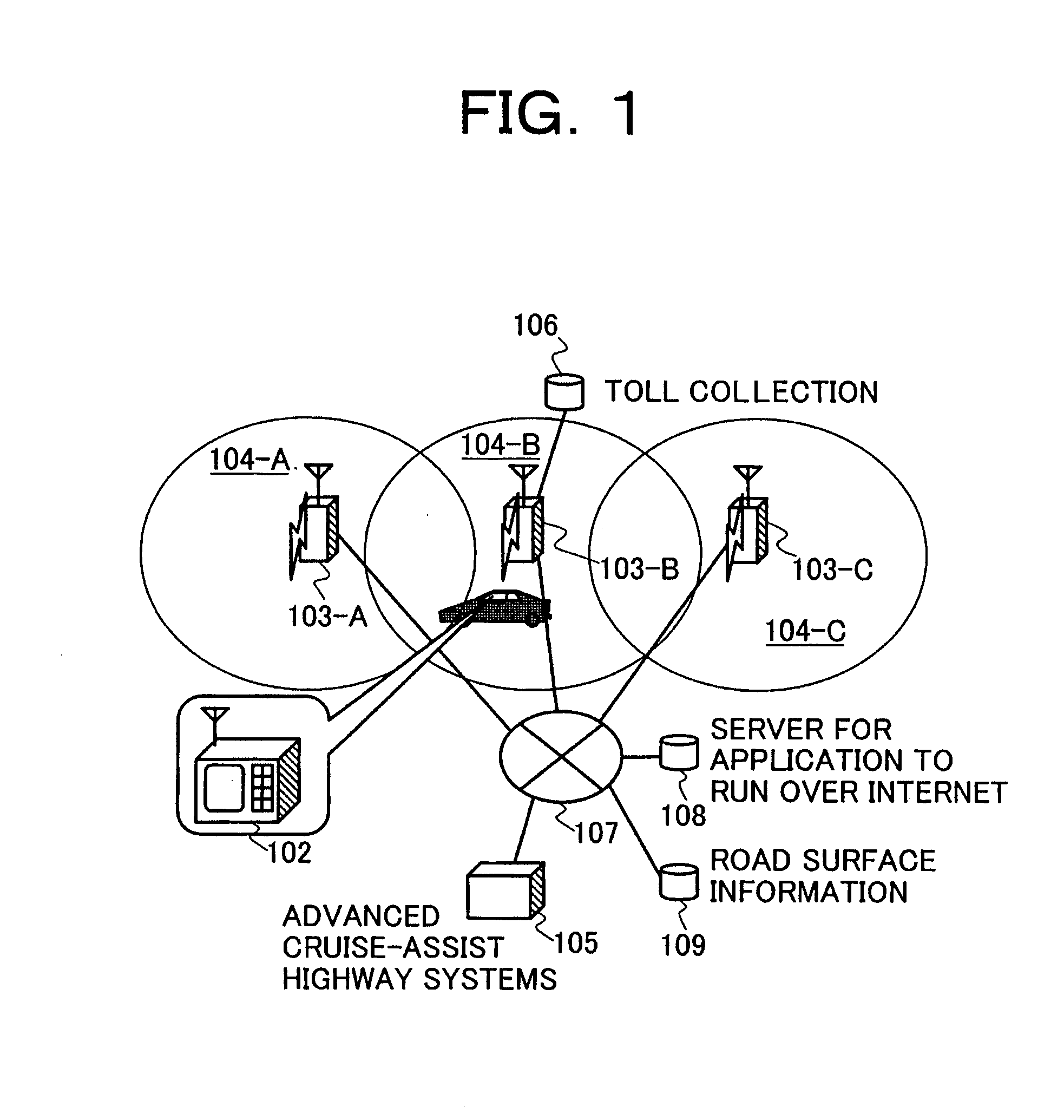
[0021]FIG. 1 shows an example of a digital radio communication system to which the present invention is applied. In this system, a mobile station 102 is mounted on a motor vehicle 101. Three base stations 103-A, B, C offer four applications. The three base stations 103-A, B, C each have corresponding cells 104-A, B, C. The three base stations 103-A, B, C are connected to an Advanced Cruise-Assist Highway Systems application center 105, a server for an application to offer road information 109, and a server for an application to operate over the internet 108 via a wired network 107. A toll collection application server 106 is connected to only the base station 103-B and thus it can offer service only in the cell 104-B of the base station 103-B. A noticeable feature of this example is that a plurality of applications coexist.

[0022]As an essential factor for the digital radio communication system to run these applications in a compatible way, it is required to make arrangements for com...


PUM


Abstract

A time slot for a connection request sent from a mobile station includes the mobile station ID and the application discrimination word of the object application for which the mobile station requests the connection. By referring to the database, a base station assigns a MDC preferentially to a mobile station issuing a connection request for calling a high priority application. The base station monitors the MDCs used for ongoing communications. If a MDC assigned to a mobile station does not satisfy a predetermined radio communication quality, other MDCs for lower priority application are freed and reassigned to the mobile station. A plurality of MDCs including the reassigned MDCs into which the same contents are encapsulated are transmitted to the mobile station.

Description

BACKGROUND OF THE INVENTION[0001]The present invention relates to a digital radio transmission method for multi-applications, making it possible to accommodate a plurality of mobile terminals and provide a plurality of applications.[0002]A personal Digital Cellular (PDC) and a Personal Handy-phone System (PHS) are currently available as digital radio communication systems. These systems adopt a Time Division Multiple Access (TDMA) method. This TDMA method operates as follows. A given channel is sectioned into time units called frames in the direction along time axis. Each frame is divided into time units called time slots. A base station assigns one of the time slots to a mobile station which is located within its service area and has requested use of a communication service. Then, the base station communicates with the mobile station within the time unit, called the time slot, that has been assigned to the mobile station every frame period. Generally, one time slot within one frame...

Claims


Application Information

Patent Timeline
IPC IPC(8): H04Q7/00H04J3/00G08G1/0967H04B7/26H04J3/16H04W4/04H04W8/26H04W16/02H04W24/00H04W72/04H04W72/10H04W74/04
CPCG07B15/063H04W72/10G08G1/0967G08G1/096716G08G1/096741G08G1/096775H04W72/048H04W72/085H04W72/51H04W72/542H04W72/56
Inventor SUZUKI, HIDEYADOI, NOBUKAZUISHIFUJI, TOMOAKI
Owner HITACHI LTD
Why Eureka
Try Eureka