Conspicuity devices and methods

a technology of visible devices and devices, applied in the direction of semiconductor devices for light sources, light and heating apparatus, protective garments, etc., can solve the problems of limited utility of passive devices, cumbersome power supply attachments that frequently accompany, and the size of devices, and achieve the effect of significant visibility

Active Publication Date: 2018-05-17
CSC GROUP
View PDF3 Cites 14 Cited by
  • Summary
  • Abstract
  • Description
  • Claims
  • Application Information

AI Technical Summary

Benefits of technology

[0053]In further accordance with the disclosure, the spectral energy distribution of the light source may be specifically adapted and configured to substantially overlap the spectral sensitivity of the human eye in photopic, mesopic and/or scotopic conditions. The overlap of the spectral distribution of the light source and the sensitivity of the human eye can be less than or equal to about 100%, about 95%, about 90%, about 85%, and so on in any suitable increments (e.g., of 1% or ...

Problems solved by technology

The main problem with such conventional devices include, for example, the size of the devices and cumbersome power supply attachments that frequently accompany them.
Another significant problem with such conventional devices are that flashlights and light projecting devices tend to generate light only in the visible region, particularly white light.
Such passive devices are of limited utility, as they do not emit any light in low visibility conditions or complete darkness.
In short, while these devices may be suitable for the particular purpose to which they address, they are not as suitable for a device th...

Method used


Image

  • Conspicuity devices and methods
  • Conspicuity devices and methods
  • Conspicuity devices and methods

Examples


example i

Spectral Energy Distribution of Lamp

Spectral Power Distribution

[0140]Light may be precisely characterized by giving the power of the light at each wavelength in the visible spectrum. The resulting spectral power distribution (SPD) contains all the basic physical data about the light and serves as the starting point for quantitative analyses of color. The SPD can be measured by a spectrophotometer.

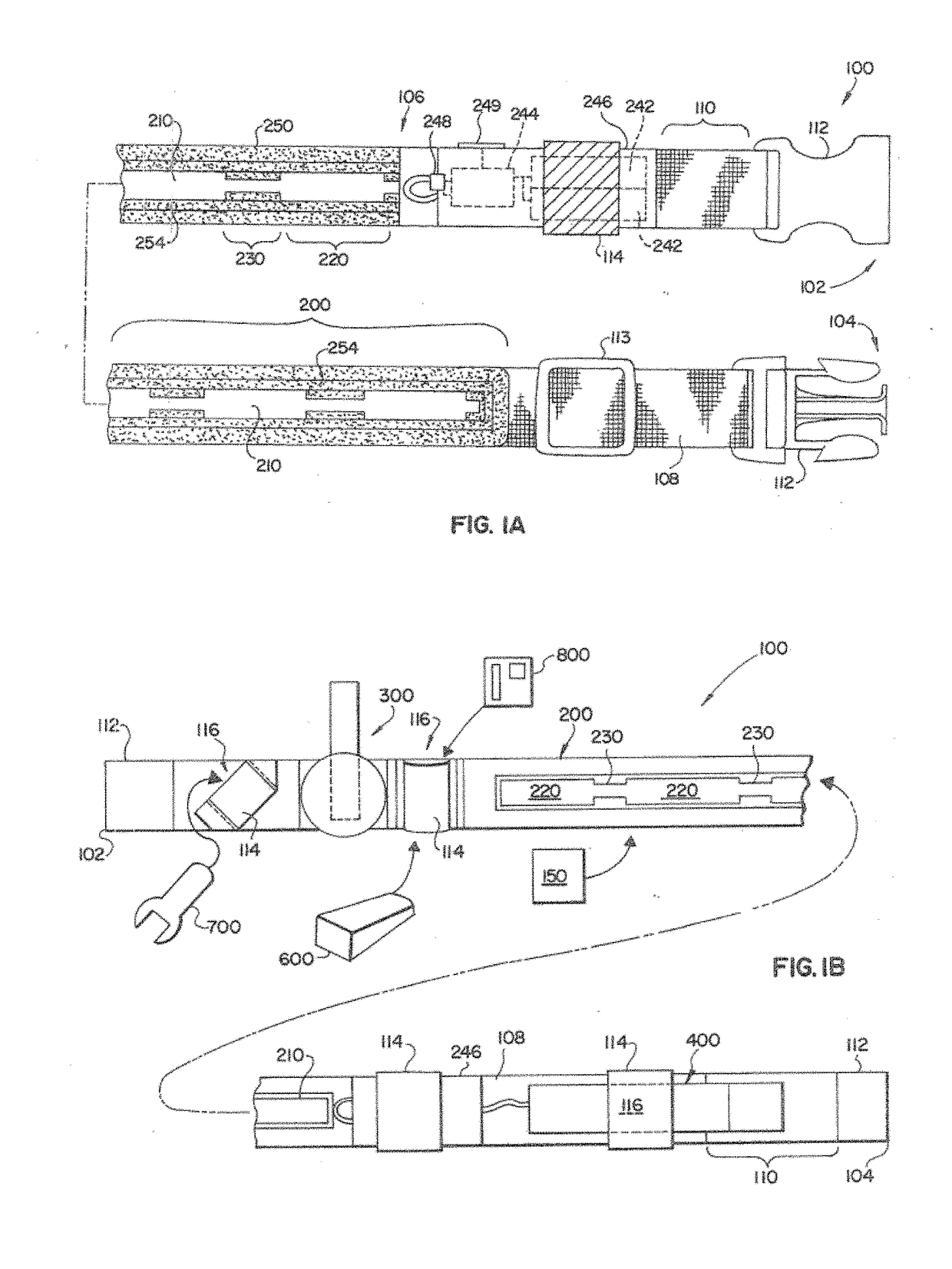
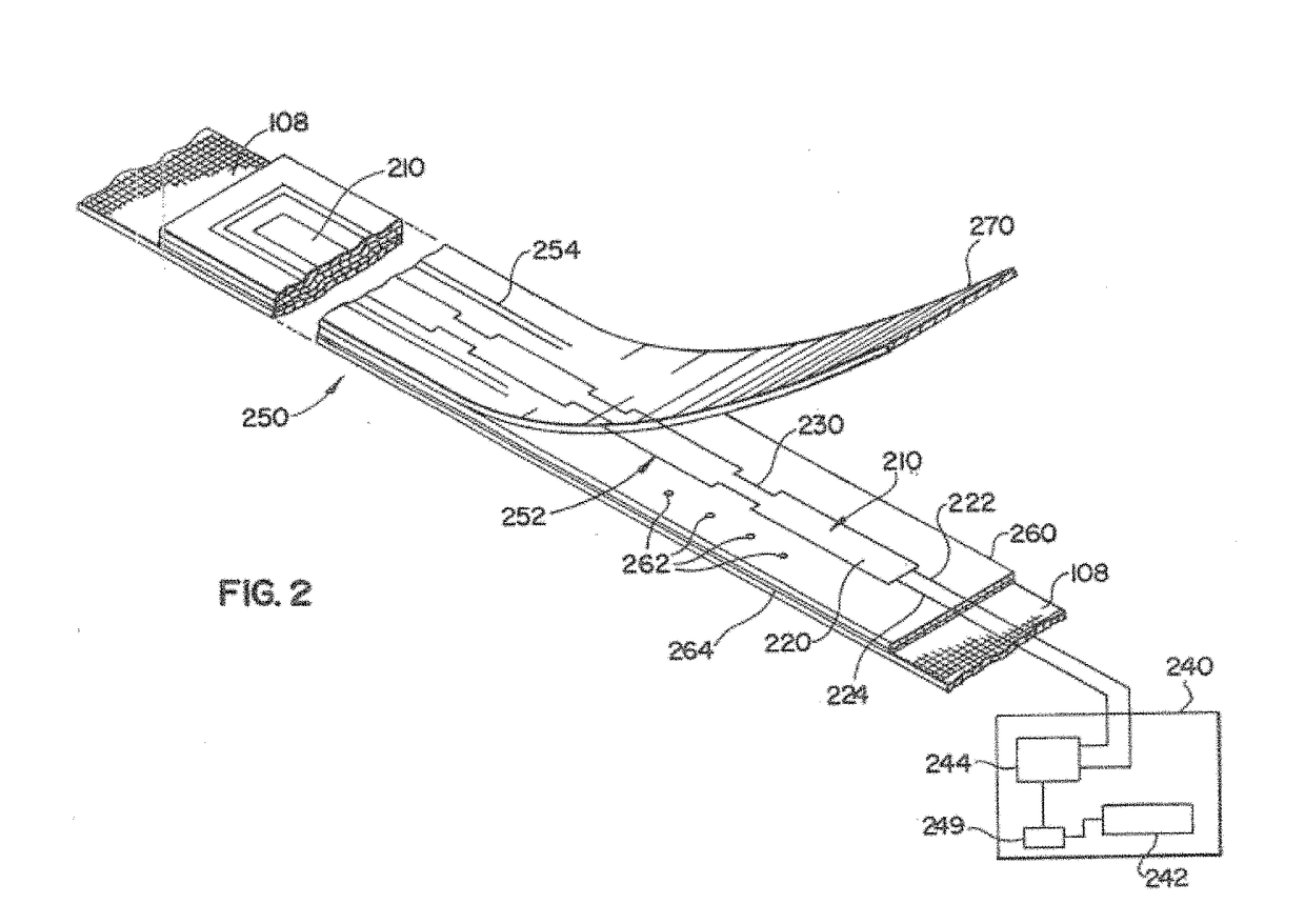
[0141]The spectral energy distribution of an exemplary embodiment of a lamp 200 made in accordance with the teachings herein was tested to determine its spectral energy distribution by an independent lighting testing laboratory. The spectral distribution test was performed with an input voltage to the inverter 244 of about 2.85 V(DC), an input current of about 144 mA (DC) an input power of 410 mW. A complete assembly with an encasement 250 was tested, having lens layer 270 in place. To perform the test, the following equipment was used by an independent testing laboratory: (i) a Xitron 2503...


PUM


Abstract

The disclosure provides conspicuity devices and methods. A first embodiment includes a glove with at least one elongate lighting device adapted and configured to admit light having an advantageous spectral energy distribution. Additional articles of clothing are provided herein for enhanced conspicuity, such as for emergency workers and athletes.

Description

CROSS-REFERENCE TO RELATED APPLICATIONS[0001]This application is a continuation-in-part of and claims the benefit of priority to U.S. patent application Ser. No. 14 / 691,193, filed Apr. 20, 2015, now U.S. Pat. No. 9,775,391, which in turn is a continuation-in-part of and claims the benefit of priority to U.S. patent application Ser. No. 13 / 350,139, filed Jan. 13, 2012, which in turn is a continuation-in-part of and claims the benefit of priority to U.S. patent application Ser. No. 12 / 106,301, filed Apr. 20, 2008, which in turn is a continuation-in part of and claims the benefit of priority to International Patent Application No. PCT / US07 / 00653, filed Jan. 10, 2007, which in turn claims the benefit of priority to U.S. Provisional Patent Application Ser. No. 60 / 757,623 filed Jan. 10, 2006, U.S. Provisional Patent Application Ser. No. 60 / 772,073 filed Feb. 10, 2006 and U.S. Provisional Patent Application Ser. No. 60 / 795,332 filed Apr. 26, 2006.[0002]This application is a continuation of...

Claims


Application Information

Patent Timeline
IPC IPC(8): A42B3/04A41D13/01A45C13/30A45F5/02F21V33/00
CPCA42B3/044A41D13/01A45C13/30A42B3/0453A45F5/02F21V33/0008A45F2200/0566F21Y2103/20F21Y2103/10F21Y2115/10B60Q2400/10A45F2200/0575F21V33/0064F21V33/008A45F5/021A45C15/06A45F3/02A45F3/04A45F3/14A45F2003/142A45F2005/002A45F2005/008
Inventor GONZALEZ, JOSEPH A.
Owner CSC GROUP
Why Eureka
Try Eureka