Radar based inverse detection sensor system

a sensor system and inverse detection technology, applied in the field ofradar based inverse detection sensor system, can solve the problems of affecting human eyes, affecting the safety of people's eyes, and the seat itself is generally more expensive, and achieves the effect of small and compact device and enhanced reflectiveness

Inactive Publication Date: 2020-08-06
NOVELIC D O O
View PDF0 Cites 6 Cited by
  • Summary
  • Abstract
  • Description
  • Claims
  • Application Information

AI Technical Summary

Benefits of technology

[0033]By observing specific object by radar system, the total reflected energy to the radar systems is dependent on the level of the scattered waves in other directions as the direction of the incident waves. Due to the fact, that if the radar is receiving antennas and on the same place where transmit antennas are, the receiving power level from specific reflections is dependent of the level of scattering waves. If the object, would have features to reduce parasitic scattering and would reflect more power in the directions, where it is illuminated, its effective radar cross section would be larger, and receiving antenna at the radar will register more receiving power. With other words object having features for having less parasitic scattering and better reflection of the illuminated radio power to the direction of the illumination is better visible in the radar signal processing, compared to the environment in its enclosure without this feature. Even if the environment has metalized surfaces, the visibility is larger, if waves may be reflected in the same way where the Illumination of the signal is presented.

Problems solved by technology

The classification of the passenger in proposed classes as a state of art solution required complex pressure sensor systems, which required power supplies, so that the seats itself are generally more expensive.
The alternative state of the art solution for applications in FIG. 2 and FIG. 3 is usage a laser sensor, which has a drawback to be influenced by dust, vapor other light sources, having hazardous influence to human eyes, it is more expensive compared to proposed system, and in some cases requests power supply on two sides, in contrast to proposed system having only one side power consumption.
The alternative state of art solution is laser beam, which has a drawback to be influenced by dust, vapor other light sources and having hazardous influence to human eyes.
The state of art solution with ToF (Time of flight) sensor, cannot differentiate if the package is full of liquid being placed on production belt, because the light is not passing through the package.

Method used


Image

  • Radar based inverse detection sensor system
  • Radar based inverse detection sensor system
  • Radar based inverse detection sensor system

Examples


Embodiment Construction

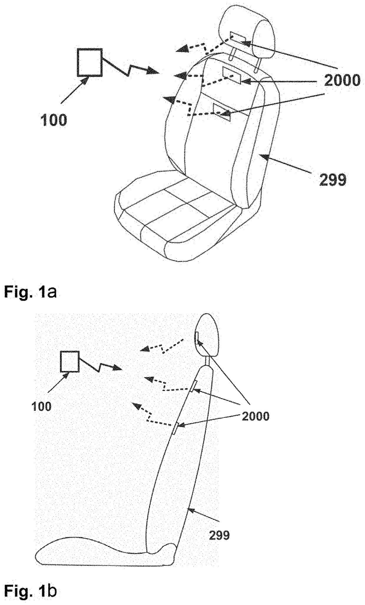
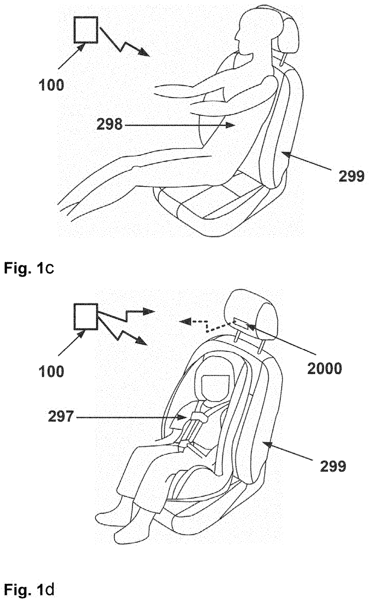
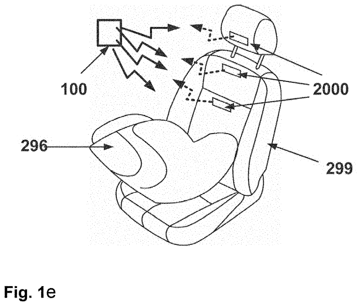
[0069]Radar based system, using frequency range of 24 GHz and 30-300 GHz comprising the one apparatus 100 with HW radar functionality, and at least two apparatuses 2000 being placed physically at the distance from apparatus 100, being integrated in the vehicle seat 299, like in FIG. 1. Apparatus 100 contains:[0070]At least one high-gain planar antenna for transmitting mm-wave radio signals 21, where the high-gain planar antenna has at least two radiation elements;[0071]At least one high-gain planar antenna for receiving mm-wave radio signals 110, where the high-gain planar antenna has at least two radiation elements; and has cross polarization, compared to antenna 21;[0072]Integrated radio front end 10, implemented in arbitrary semiconductor technology, having on-chip integrated mm-wave voltage control oscillator, mm-wave power amplifier, at least one mm-wave IQ demodulator, digital control interface, power supply;[0073]Digital processing functionality 30 with arbitrary hard wired a...


PUM


Abstract

The present invention discloses radar sensor system, operating in 24 GHz to 300 GHz frequency band, and its method of operation, comprising utilization of the passive markers, reflecting radio wave in the direction of illumination advantageously in cross polarization manner. The proposed system can detect if on the vehicle seat a baby, kid or adult average size person is sitting. The proposed system can detect intrusion, non-occupied area, belt speed, rotation speed and if the package is filled with sufficient level of liquids.

Description

[0001]MM-wave radar sensor system described by apparatuses and method of operation is proposed addressing several applications. The proposed system is advantageously used for application regarding detection and classification of the human beings on the seats. Classes of the human being using seats detected by the proposed system are: adult, kid, being defined as human person smaller than average size of the human, and baby. The seat does not necessarily have the power supply. The same proposed system can be used for the classification of the objects having different heights and sizes, intrusion control, general space occupation, vehicle height detection and speed detection of latterly positioned objects and liquids.TECHNICAL FIELD[0002]Radar sensor system with its method of operation using 24 GHz-300 GHz frequency band is introduced.BACKGROUND ART[0003]The specific problems or classifying the people regarding its size is addressed by using mm-wave radar sensor frequencies. The propo...

Claims


Application Information

Patent Timeline
Patent Type & Authority Applications(United States)
IPC IPC(8): G01S13/04G01S7/03
CPCG01S7/03G01S13/04G01S7/024G01S7/032G01S7/354G01S7/411G01S7/415G01S13/876G01S13/88G01S13/931G01S2013/9329H01Q21/0018B60N2/002B60R21/01534G01S13/56
Inventor DARKO, TASOVACDEJAN, RAKICBRANKOVIC, VESELINMIHAJLOVIC, VELJKO
Owner NOVELIC D O O
Why Eureka
Try Eureka