Inductive power transfer apparatus with improved coupling

a technology of inductive power transfer and coupling, which is applied in the direction of electrical equipment, transformers, inductances, etc., can solve the problems of prone to failure, unfavourable environment for power distribution, and high physical stress on roads,

Inactive Publication Date: 2018-05-17
3I INNOVATION
View PDF0 Cites 6 Cited by
  • Summary
  • Abstract
  • Description
  • Claims
  • Application Information

AI Technical Summary

Benefits of technology

[0012]In one embodiment the flange means is provided on selected parts of the body to provide one or more recesses whe

Problems solved by technology

These systems generally have unfavourable environments for power distribution.
For example roadways are subject to considerable physical stresses due to large fast moving vehicles, illuminated road studs that are powered using fixed or hard wired connections are difficult to wire into the roadway, and are prone to failure due to stresses from vehicles that can physically move the stud or the adjacent road surface and allow foreign matter such as water or dirt to interfere with the wired connections.
One of the difficulties with IPT systems is providing good coupling between the primary conductive path (described in more detail below with reference to FIG. 1), and the pick up or pick-ups (i.e. the secondary units) to which power is transferred inductively from the primary conductors.
The increased curre

Method used


Image

  • Inductive power transfer apparatus with improved coupling
  • Inductive power transfer apparatus with improved coupling
  • Inductive power transfer apparatus with improved coupling

Examples


Embodiment Construction

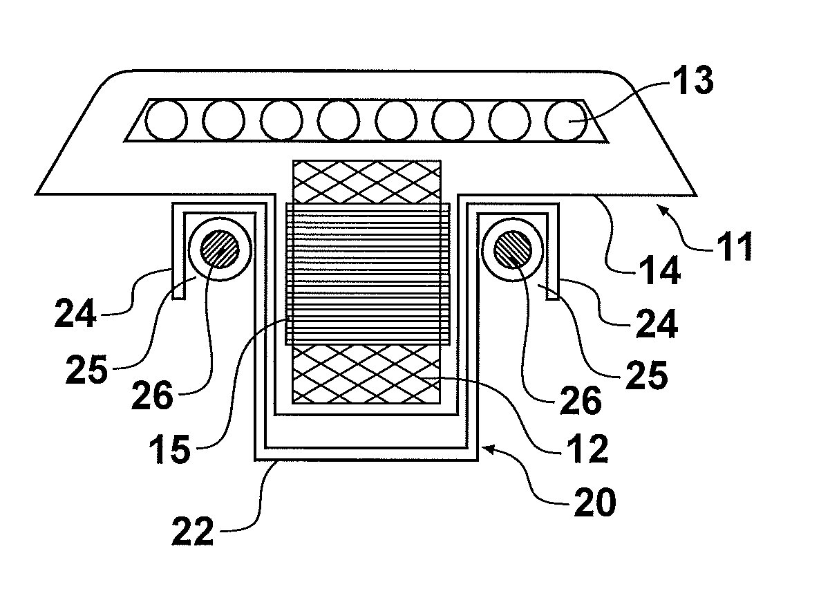
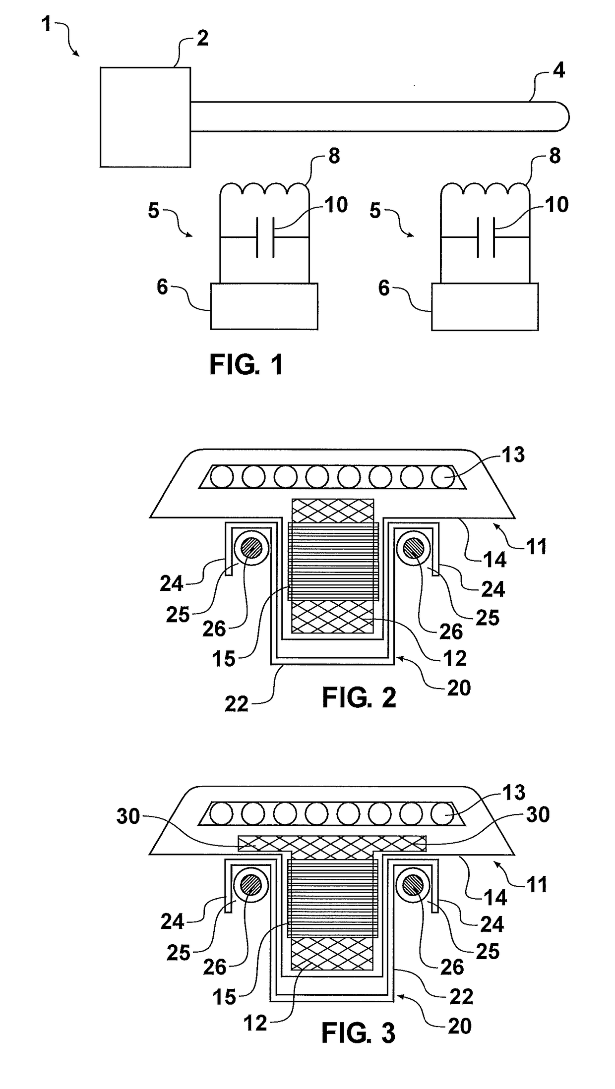
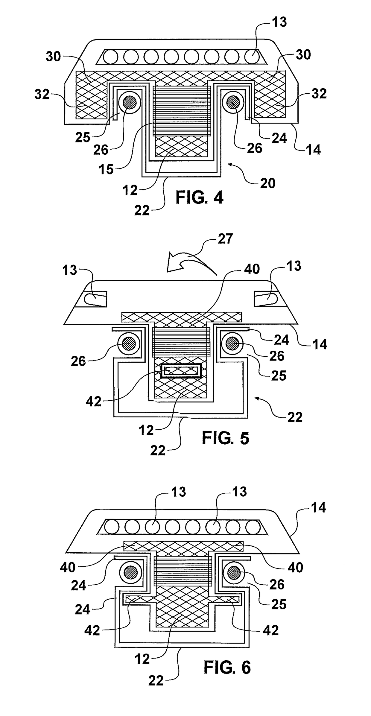
[0040]Referring to FIG. 1, the basic structure of an IPT power supply (also sometimes referred to as an inductively coupled power transfer (ICPT) power supply system or a contactless power supply system) is shown generally referenced 1. The system generally comprises two electrically isolated parts. The first part consists of a power supply 2 which may comprise a resonant converter for example. The power supply supplies electrical energy to a primary conductive path 4 so that an alternating current is provided in the primary conductive path. The primary conductive path is usually provided in the form of an elongated cable or track from which one or more of the second parts (commonly referred to as “pick-ups”) 5 are located. The primary conductive path may be provided on, within, or beneath a roadway for example, and secondary pick-ups 5 which may comprise lighting elements such as illuminated road studs are adhered to the surface of the roadway.

[0041]Each of the pick-ups 5 includes ...


PUM


Abstract

Apparatus for an Inductive power transfer system, particularly adapted for lighting systems such as road studs, includes a pick-up core (12) having a flange portion (30), and a receiver (20) which includes a recess (25) for locating a primary conductor (26).

Description

FIELD OF THE INVENTION[0001]This invention relates to apparatus and systems for transferring power inductively i.e. wirelessly. Such systems are commonly known as inductive power transfer (IPT) systems. The invention has particular, but not sole, application to IPT systems having stationary pick-ups (otherwise known as secondaries). One application of the invention includes lighting systems for roadways.[0002]The operation of inductive power transfer systems can be found in the prior art, for example in U.S. Pat. No. 7,675,197, the contents which are incorporated herein by reference.[0003]As stated in U.S. Pat. No. 7,675,197, inductive power transfer systems have significant benefits in a number of applications. One such application is lighting systems for roadways, tunnels, swimming pools and aircraft. These systems generally have unfavourable environments for power distribution. For example roadways are subject to considerable physical stresses due to large fast moving vehicles, i...

Claims


Application Information

Patent Timeline
IPC IPC(8): H02J50/10H01F38/14
CPCH02J50/10H01F38/14
Inventor MAUD, CHARLES DARRELL
Owner 3I INNOVATION
Why Eureka
Try Eureka