Self-Driving Telescopic Post

a telescopic post and self-driving technology, applied in the direction of rod connection, variable height table, gearing, etc., can solve the problem of long time-consuming and laborious to extend the telescopic uni

Inactive Publication Date: 2018-05-24
TCT GRP CO LTD
View PDF4 Cites 20 Cited by
  • Summary
  • Abstract
  • Description
  • Claims
  • Application Information

AI Technical Summary

Benefits of technology

[0005]To achieve the foregoing objective, the self-driving telescopic post includes a cap, a brake, a directional bearing and an axle. The cap includes comprising a central aperture in communication with a chamber. The brake is inserted in the chamber. The directional bearing is inserted in the cap and engaged with the brake. The axle is inserted in the central aperture and supported by the directional bearing. The axle is allowed to rotate in a first sense of direction relative to the directional bearing so that the brake does not interfere with the rotation of the axle in the first sense of direction via the directional bearing. The axle is prevented from rotation in a second sense of direction relative to the directional bearing so that the brake interferes with the rotation of the axle in the second sense of direction via the directional bearing.

Problems solved by technology

However, a long threaded rod means a long period of time for extending the telescopic unit from a minimum length to a maximum length.

Method used


Image

  • Self-Driving Telescopic Post
  • Self-Driving Telescopic Post
  • Self-Driving Telescopic Post

Examples


Embodiment Construction

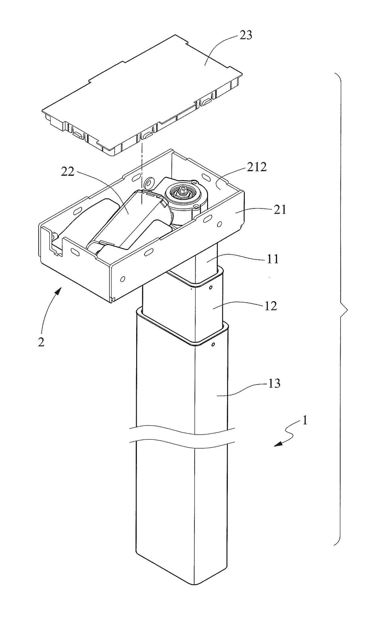
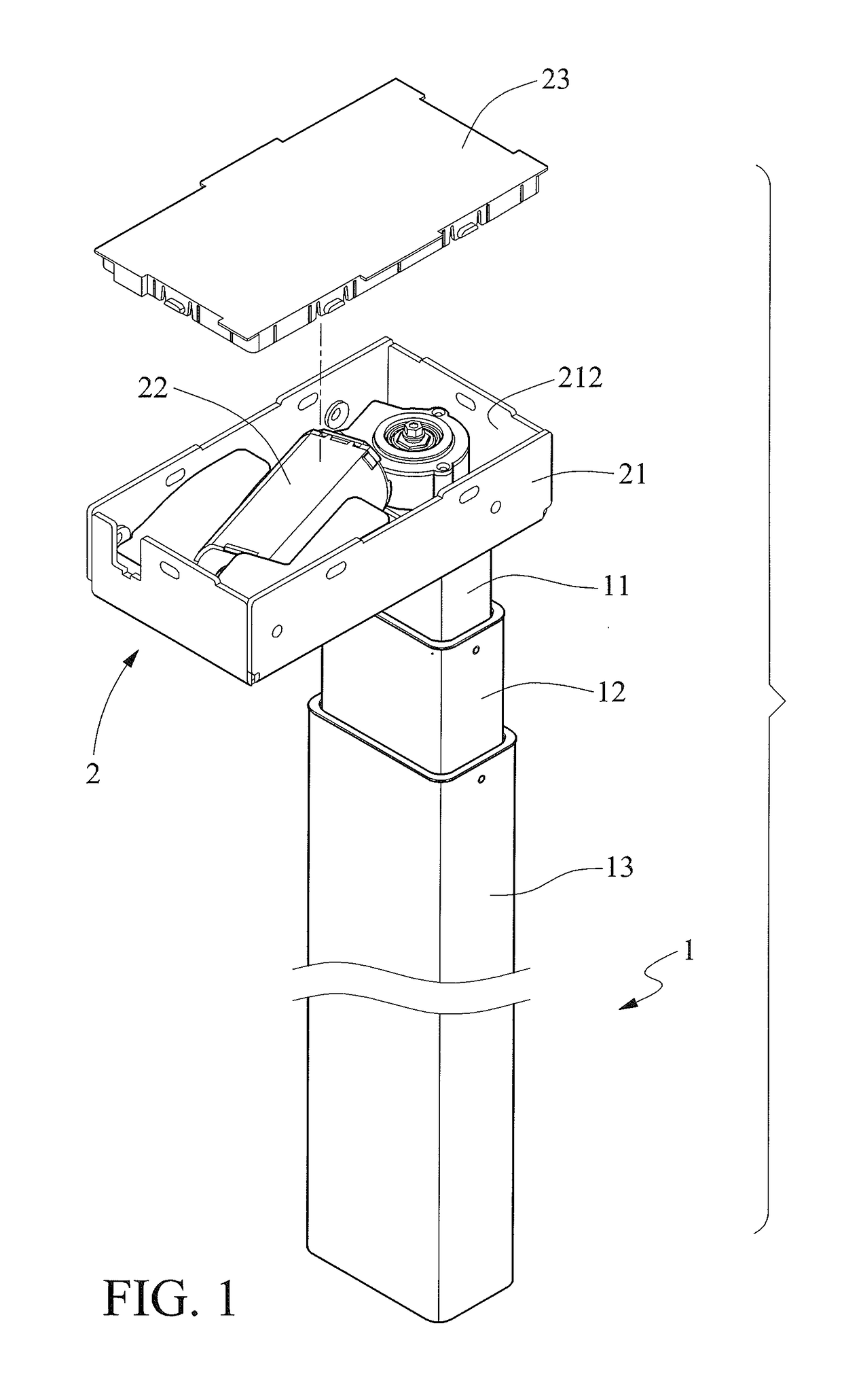
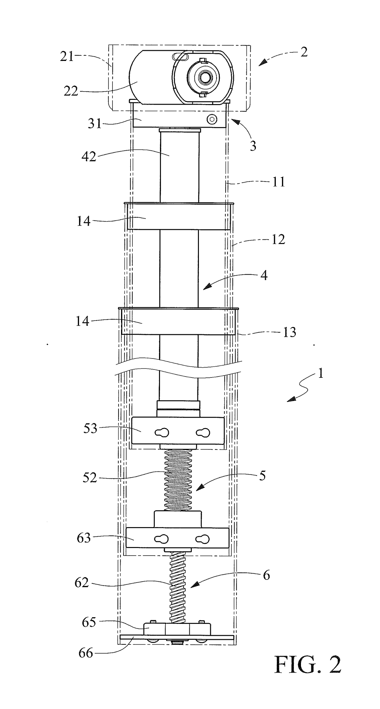
[0018]Referring to FIGS. 1 through 10, a self-driving telescopic post includes a telescopic unit 1, a power unit 2, an upper transmission unit 3, a lower transmission unit 4, an internal tube-driving unit 5 and a middle tube-driving unit 6 in accordance with the preferred embodiment of the present invention. The upper transmission unit 3 connects the power unit 2 to the lower transmission unit 4. The upper transmission unit 3 transfers power to the power unit 2 from the lower transmission unit 4. Moreover, the upper transmission unit 3 selectively exerts a braking force.

[0019]Referring to FIGS. 1, 2 and 6 to 8, the telescopic unit 1 includes an internal tube 11, a middle tube 12, an external tube 13 and two rings 14. The internal tube 11 includes apertures 112. Each of the apertures 112 includes a larger portion and a smaller portion. The middle tube 12 includes apertures 122. Each of the apertures 122 includes a larger portion and a smaller portion. Each of the apertures 112 is ali...


PUM


Abstract

A self-driving telescopic post includes a cap, a brake, a directional bearing and an axle. The cap includes comprising a central aperture in communication with a chamber. The brake is inserted in the chamber. The directional bearing is inserted in the cap and engaged with the brake. The axle is inserted in the central aperture and supported by the directional bearing. The axle is allowed to rotate in a first sense of direction relative to the directional bearing so that the brake does not interfere with the rotation of the axle in the first sense of direction via the directional bearing. The axle is prevented from rotation in a second sense of direction relative to the directional bearing so that the brake interferes with the rotation of the axle in the second sense of direction via the directional bearing.

Description

BACKGROUND OF INVENTION1. Field of Invention[0001]The present invention relates to a telescopic post of a table and, more particularly, to a self-driving telescopic post.2. Related Prior Art[0002]A conventional self-driving telescopic post of a table includes a telescopic unit, a carrier, a transmission unit, and a worm and worm gear for connecting the carrier to the transmission unit. The telescopic unit includes an internal tube movably inserted in an external tube. The transmission unit includes a single threaded rod for driving an internal tube relative to the external tube. Thus, the elevation of the table is changeable. The length of the single threaded rod determines how much the elevation of the table is changeable. However, a long threaded rod means a long period of time for extending the telescopic unit from a minimum length to a maximum length. Moreover, the lifting and lowering of the table is conducted at a same pace. However, lifting of the table at high speed is desir...

Claims


Application Information

Patent Timeline
Patent Type & Authority Applications(United States)
IPC IPC(8): A47B9/20F16H25/20F16M11/28
CPCA47B9/20F16H25/20F16M11/28F16M11/26F16M11/24F16H2025/2084A47B2200/0054A47B2200/0051A47B2200/005A47B2200/0035F16H2025/2059F16M11/20A47B9/04A47B2200/0057F16B7/14F16H25/2056F16H2025/2031
Inventor WU, TIGER
Owner TCT GRP CO LTD
Why Eureka
Try Eureka