

Sterilization device
a technology of sterilization device and flow path, which is applied in the direction of application, disinfection, specific water treatment objectives, etc., can solve the problems of increasing manufacturing cost or necessary parts, and achieve the effect of improving sterilization capability and simple flow path structur
- Summary
- Abstract
- Description
- Claims
- Application Information
AI Technical Summary
Benefits of technology
Problems solved by technology
Method used
Image

Examples
first embodiment
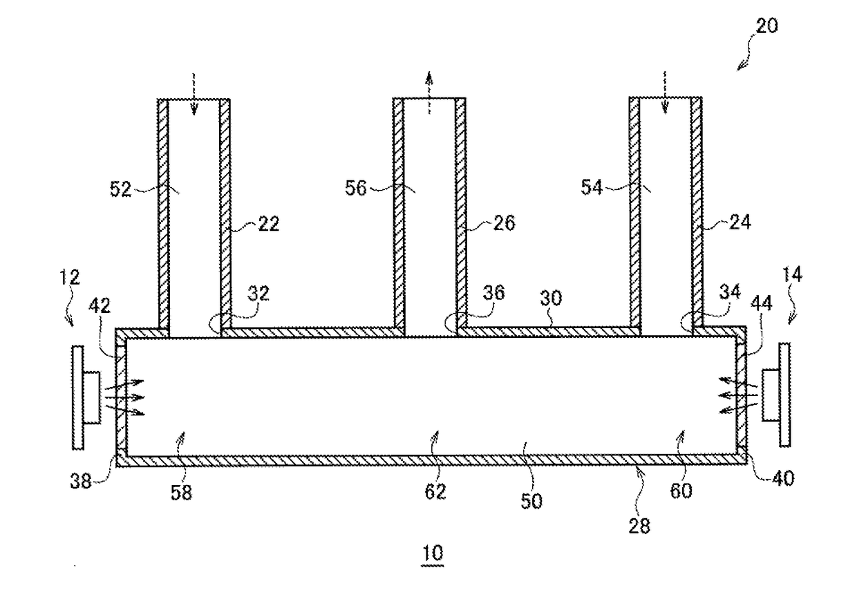
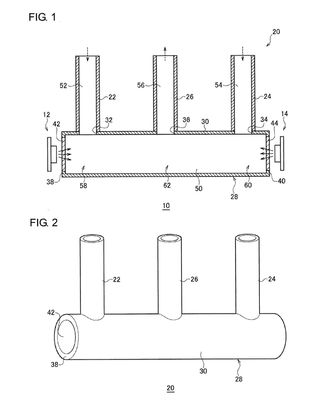
[0023]FIG. 1 is a diagram that schematically shows a configuration of a sterilization device 10 according to the embodiment, and FIG. 2 is an external perspective view that schematically shows a flow path structure 20 shown in FIG. 1. The sterilization device 10 comprises multiple light sources (a first light source 12, a second light source 14) and the flow path structure 20. The flow path structure 20 is sectioned into a treatment chamber 50, multiple inflow paths (a first inflow path 52, a second inflow path 54), and an outflow path 56. The sterilization device 10 irradiates a fluid flowing through the first inflow path 52 or second inflow path 54 into the treatment chamber 50 with ultraviolet light emitted by the first light source 12 and second light source 14, and the fluid sterilized by the irradiation of ultraviolet light flows out through the outflow path 56.
[0024]The flow path structure 20 includes a first inflow pipe 22, a second inflow pipe 24, an outflow pipe 26, and a ...
first modification
(First Modification)
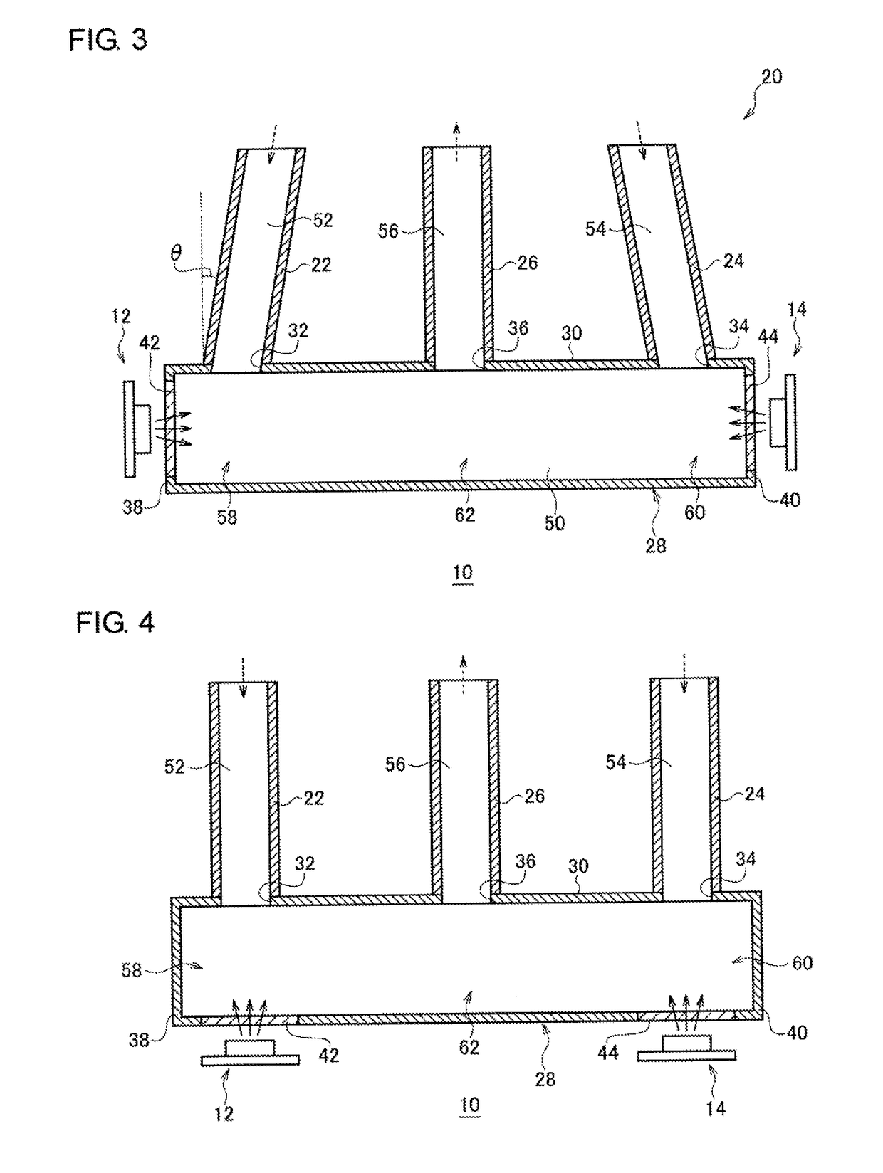
[0037]FIG. 3 is a sectional view that schematically shows a configuration of the sterilization device 10 according to a modification. The present modification differs from the aforementioned embodiment in that each of the first inflow path 52 and the second inflow path 54 is provided so as to extend in an oblique direction that intersects both a longitudinal direction and a radial direction of the treatment chamber 50. In the following, the modification will be described mainly for the differences from the aforementioned embodiment.
[0038]The first inflow pipe 22 is attached to the first inlet port 32 so as to extend in a direction inclined at an angle θ to a radial direction of the treatment chamber 50. The first inflow pipe 22 is provided so that a fluid flowing through the first inflow path 52 toward the treatment chamber 50 has a velocity component from the first inlet, port 32 toward the first end surface wall 38. Accordingly, the first inflow pipe 22 is prov...
second modification
(Second Modification)
[0044]FIG. 4 is a sectional view that schematically shows a configuration of the sterilization device 10 according to another modification. The present modification differs from the aforementioned embodiment in that the first window 42 for transmitting ultraviolet light emitted by the first light source 12 and the second window 44 for transmitting ultraviolet light emitted by the second light source 14 are provided on the side wall 30. In the following, the modification will be described mainly for the differences from the aforementioned embodiment.
[0045]The first window 42 is provided on the side wall 30 near the first end surface wall 38, such as at a position opposite to the first inlet port 32. Also, the second window 44 is provided on the side wall 30 near the second end surface wall 40, such as at a position opposite to the second inlet port 34. The first light source 12 is disposed near the first window 42 so as to emit ultraviolet light toward the first ...
PUM
| Property | Measurement | Unit |
|---|---|---|
| peak wavelength | aaaaa | aaaaa |
| velocity | aaaaa | aaaaa |
| distance | aaaaa | aaaaa |
Abstract
Description
Claims
Application Information