Nte display systems and methods with optical trackers

a display system and optical tracker technology, applied in the field of nte, can solve the problems of inability to achieve satisfactory performance capabilities, large size of display system, and large size of display system, and achieve the effects of extending the capabilities of the tracker system, enhancing the ability to detect small changes, and enhancing the capability of detecting

Active Publication Date: 2018-05-24
HONEYWELL INT INC
View PDF5 Cites 15 Cited by
  • Summary
  • Abstract
  • Description
  • Claims
  • Application Information

AI Technical Summary

Benefits of technology

[0073]Another optical modifier 1176 is shown in FIG. 11. Optical modifier 1176 is similar to the flat optical modifier 976 of FIG. 9, but here, multiple reflections from the parallel surfaces are considered. The surfaces of modifier 1176 may be uncoated or optionally have coatings which adjust the balance between reflection and transmission at the surfaces. A similar effect may be achieved by using air-spaced partially reflective mirrors or beamsplitters, but FIG. 11 assumes a refractive index n>1. As with FIG. 9, fiducial position 1174 is not impacted by the optical element 1176. Fiducial position 1188 in this case results in multiple apparent fiducial positions, e.g., positions 1178 and 1176, due to optical rays 1186 traveling to camera unit 1160. The optional inclusion of rays 1182 and 1184 again adds enhanced capability for detecting and quantifying the impact of spatial characteristics in the presence of optical modifier 1176.
[0074]Another exemplary embodiment is shown in FIG. 12. Here, optical modifier 1276 includes two specularly reflective mirrors placed at fixed angles with respect to tracker display unit 1270. Rather than camera unit 1260 detecting a single image of fiducial symbol 1288, multiple images of fiducial symbol 1288 are captured via optical rays 1286. Light emitted or modulated by display unit 1270 at the fiducial symbol 1288 location includes light reflected by optical modifiers 1276, and for the given configuration results in apparent copies of symbol 1288 at locations 1278. As with FIGS. 9-11, these modified and/or additional points provide additional information with which to pre-process or post-process the captured results to determine the spatial characteristics. Each of the embodiments involving optical modifiers effectively introduces data beyond what is available from the planar tracker display units 970, 1070, 1170 and 1270 alone, and enhances the ability to discern small changes in such a multiple degree of freedom tracking scenario. The ability to modify the fiducial symbols in this embodiment allows the system to position the fiducial symbol(s) 1288 such that multiple images 1278 are present and visible to camera unit 1260. Lines and curves can be incorporated into fiducial symbol 1288, and the relationship between symbol 1288 and images 1278 captured and analyzed.
[0075]Several types of optical modifiers have been presented, including refractive, reflective and combination elements, and modifiers having optical power and without optical power, but these are no

Problems solved by technology

Known tracking technologies include inertial, magnetic, ultrasonic, and camera-based optical systems, although m

Method used


Image

  • Nte display systems and methods with optical trackers
  • Nte display systems and methods with optical trackers
  • Nte display systems and methods with optical trackers

Examples


Embodiment Construction

[0017]The following detailed description is merely exemplary in nature and is not intended to limit the invention or the application and uses of the invention. As used herein, the word “exemplary” means “serving as an example, instance, or illustration.” Thus, any embodiment described herein as “exemplary” is not necessarily to be construed as preferred or advantageous over other embodiments. All of the embodiments described herein are exemplary embodiments provided to enable persons skilled in the art to make or use the invention and not to limit the scope of the invention which is defined by the claims. Furthermore, there is no intention to be bound by any expressed or implied theory presented in the preceding technical field, background, brief summary, or the following detailed description.

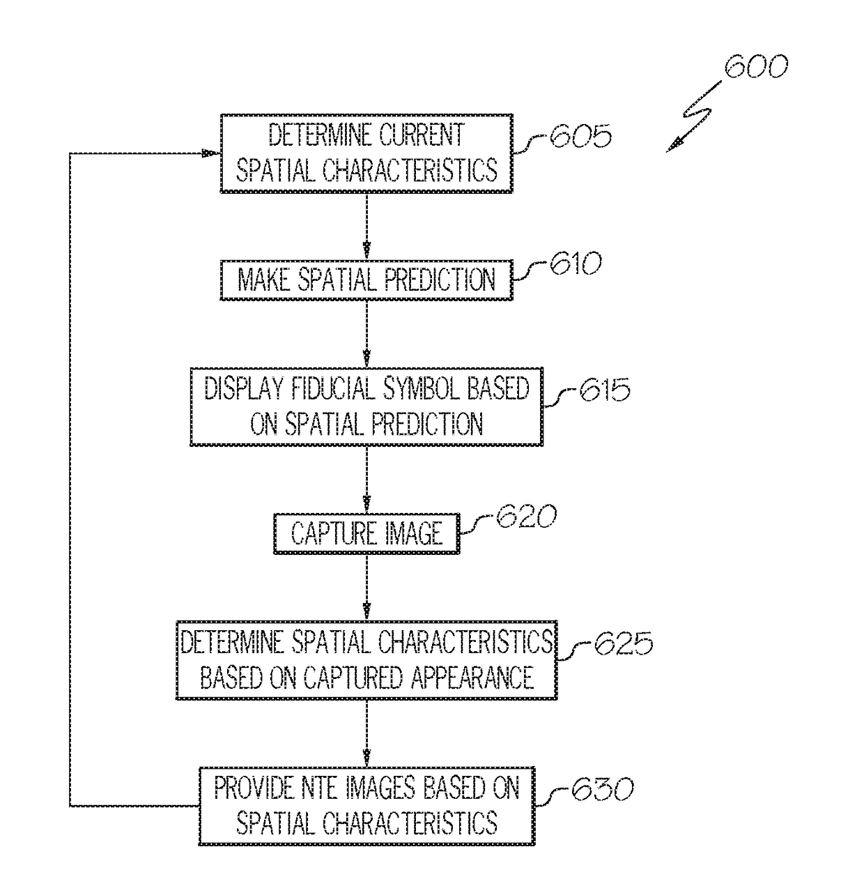
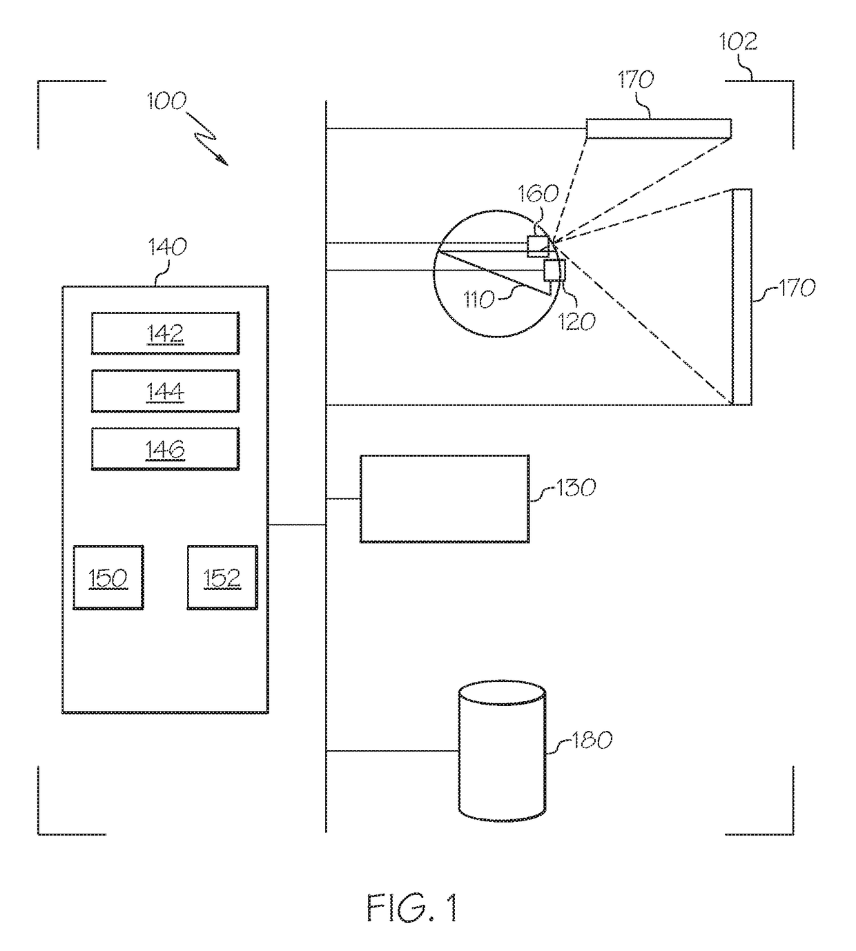
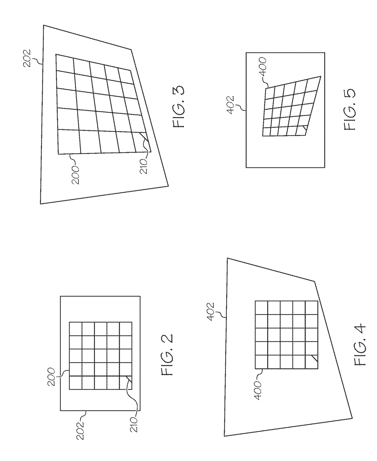
[0018]In the exemplary embodiments described below, near-to-eye (NTE) display systems and methods are used to track the spatial characteristics of a head of a user to determine a visual perspec...


PUM


Abstract

An optical tracker system is provided for tracking a location and orientation of a first object. The system includes a prediction module configured to determine a predicted location and orientation of the first object as a spatial prediction; a display module configured to generate display commands for a fiducial symbol based on the spatial prediction; a display unit configured to display the fiducial symbol based on the display commands; a camera unit configured to capture an image of the fiducial symbol displayed on the display device as a captured appearance; and a position determination module coupled to the camera unit and configured to receive the image from camera unit. The position determination module is configured to identify the fiducial symbol and determine the location and the orientation of the first object based on the captured appearance of the fiducial symbol.

Description

TECHNICAL FIELD[0001]The present invention generally relates to near-to-eye (NTE) display systems and methods, and more particularly relates to NTE display systems and methods with improved high speed, high precision optical trackers.BACKGROUND[0002]In recent years, near-to-eye (NTE) display systems have been developed and are becoming increasingly popular. Depending upon the particular end-use environment, these systems include NTE display units coupled to a helmet or headset of a user, and thus move with the changing location and angular orientation of the user's head. This advantageously allows the displayed information to be visible to the user regardless of the position, i.e. location and / or orientation of the head. It may thus be appreciated that tracking arrangements function to determine the location and orientation of the head in one or more degrees-of-freedom (e.g., x, y, and z, and pitch, yaw, and roll) in order to enable the overall functionality of an NTE display system...

Claims


Application Information

Patent Timeline
IPC IPC(8): G06F3/01G06T7/00G02B27/32G02B27/01
CPCG06F3/012G06T7/0044G02B27/32G02B2027/014G02B27/0172G06T2207/30204G02B2027/0138G02B27/0179G02B27/0093G02B2027/0187G06T7/74G02B27/017
Inventor LARSON, BRENT D.
Owner HONEYWELL INT INC
Why Eureka
Try Eureka