
Smart water supply valve system and method for controlling same

a water supply valve and intelligent technology, applied in the direction of valves, mechanical devices, engine components, etc., can solve the problems of failure to automatically and variably supply the appropriate amount of water, etc., to prevent unnecessary waste of water

Active Publication Date: 2018-05-31
LG ELECTRONICS INC
View PDF32 Cites 32 Cited by
  • Summary
  • Abstract
  • Description
  • Claims
  • Application Information

AI Technical Summary

Benefits of technology

[0016]According to one embodiment of the present invention, a system, which solves the problem of the related art and may drain water by optimizing the amount of water output from a water supply valve system in accordance with intention of a user, is provided.
[0017]According to another embodiment of the present invent

Problems solved by technology

However, this related art water supply valve system has caused waste of unnecessary water by allowing a user to manually manipulate to control the amount of water or flowing water for a certain time period in accordance with a signal sensed by the infrared se

Method used


Image

  • Smart water supply valve system and method for controlling same
  • Smart water supply valve system and method for controlling same
  • Smart water supply valve system and method for controlling same

Examples


first embodiment

[0068]First of all, as the first embodiment, there may be a method for allowing an object (for example, user) to directly touch the temperature sensor 723. In this case, it is required to design the smart valve system 700 such that the temperature sensor 723 is arranged on the smart valve system to allow a user to easily touch the temperature sensor 723.

second embodiment

[0069]As a second embodiment, even though the object does not directly touch the temperature sensor 723, if the object is close to the temperature sensor 723, a peripheral temperature is changed necessarily. The temperature sensor 723 can estimate the temperature of the object by sensing the changed peripheral temperature.

[0070]On the other hand, FIG. 7 relates to an embodiment contrary to the status of FIG. 6. First of all, as shown in FIG. 7(a), the smart water supply valve system 800 includes an infrared sensor 821, a camera 822, and a temperature sensor 823, and may be designed such that some of the sensors may be used in accordance with the need of the person with ordinary skill in the art.

[0071]And, as shown in FIG. 7(a), it is assumed that a temperature of an object is sensed by the temperature sensor 823. For example, as shown in FIG. 7(a), if it is determined that the temperature of the object is less than A° C., as shown in FIG. 7(b), the amount of the water discharged thr...

third embodiment

[0083]The third embodiment will be described with reference to FIG. 8. As shown in FIG. 8(a), it is assumed that a mobile device 950 executes navigation and sets ‘my house’ to a destination. At this time, as shown in FIG. 8(b), a mobile device 951 outputs a message for requiring whether to prepare for a bath mode. If the user selects the bath mode, the mobile device calculates an estimated arrival time from the current position to the destination ‘house’ and transmits time information to the smart water supply valve system.

[0084]The smart water supply valve system that has received the time information is designed to fill the bathtub with the amount of water and a temperature, which are set by the user. Particularly, the smart water supply valve system according to another embodiment of the present invention automatically changes the temperature on the basis of the time information. For example, if the arrival time of the user is delayed, the smart water supply valve system is desig...


PUM


Abstract

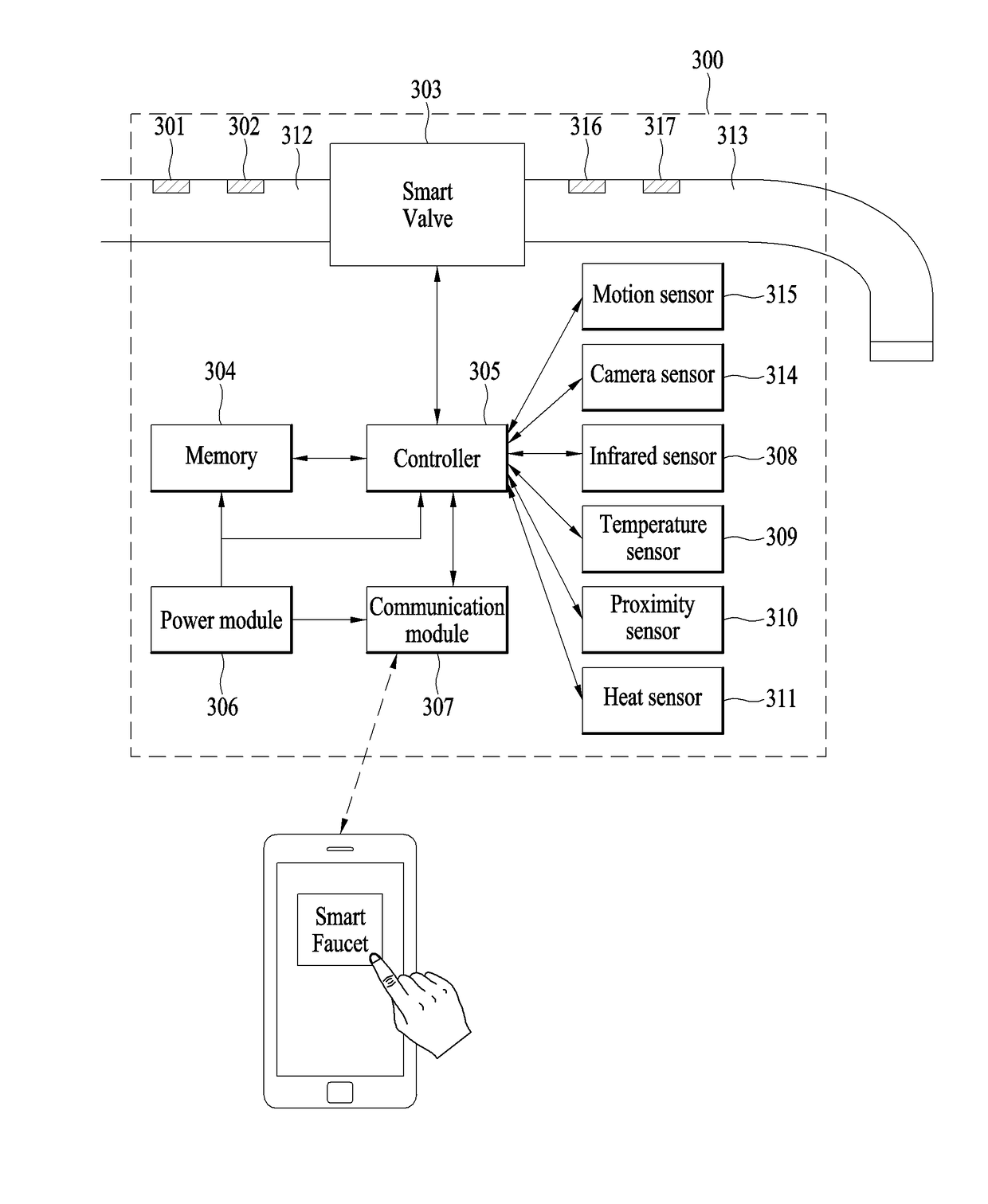
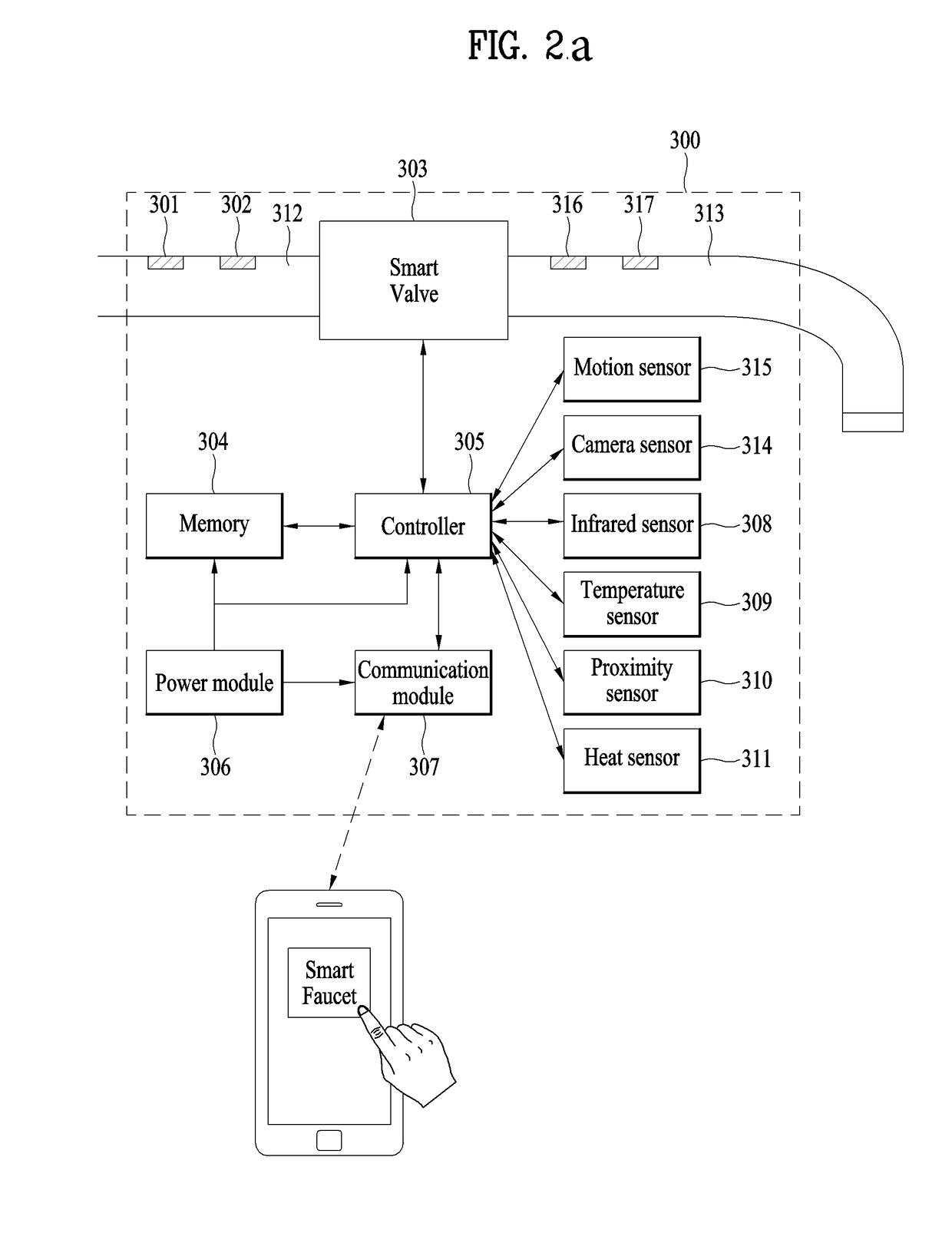
A smart water supply valve system according to an embodiment of the present invention comprises an inflow unit for being supplied with water through one or more pipes; a valve for allowing/suspending the flow of water input through the inflow unit; a first sensing unit for sensing the pressure or flow rate of water unit input through the input unit; a second sensing unit for sensing at least one of the movement, the shape, and the heat distribution of an object; a controller for controlling the amount of opening/closing of the valve or the flow rate of water on the basis of sensing outputs from the first and second sensing units; and an outflow unit for discharging water supplied from the pipe.

Description

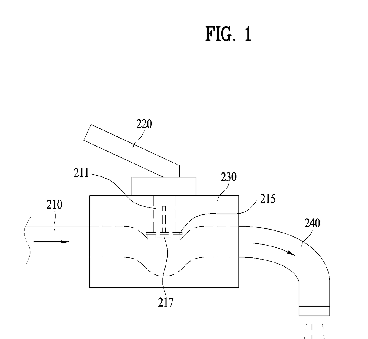
TECHNICAL FIELD[0001]The present invention relates to a smart water supply valve system, and more particularly, to a smart water supply valve system and a method for controlling the same. For example, the present invention is a technology applicable to all water supply valve systems fixed to a wash stand, a bathtub, a toilet or kitchen sink provided in homes or public facilities.BACKGROUND ART[0002]FIG. 1 is a cross-sectional view illustrating a water supply valve system according to the related art. The water supply valve according to the related art is connected to an inlet 210 and an outlet 240, and may manually control the amount of water by means of a valve 220. There is a latch 211 for opening or closing a lock plate 215 by controlling the valve 220. Moreover, a lock plate fastening screw 217 is designed at a lower end of the lock plate 215.[0003]A water supply valve system which has been recently introduced is designed such that an infrared sensor is fixed to a position near ...

Claims


Application Information

Patent Timeline
IPC IPC(8): E03C1/05E03C1/04F16K37/00
CPCE03C1/057E03C1/04F16K37/005E03C2001/0418F16K31/02E03C1/055E03C1/05
Inventor PARK, JONGSEOK
Owner LG ELECTRONICS INC
Learn More