Positioning apparatus

Active Publication Date: 2018-05-31
DR ING H C F PORSCHE AG
5 Cites 0 Cited by

AI-Extracted Technical Summary

Problems solved by technology

Moreover, the claimed positioning apparatu...

Method used

[0036]A double arrow 37 indicates that the tubular fluid container 5 can be rotated via the lever 36 either in the free rotational direction (21 in FIG. 1) or in the posi...

Benefits of technology

[0004]The device described herein is intended to simplify the positioning of a tubular fluid container in an el...

Abstract

A positioning apparatus for positioning a tubular fluid container in an elongate carrier which is configured as a hollow profile. In order to simplify the positioning of the tubular fluid container, the positioning apparatus includes spring elements, by way of which the tubular fluid container is positioned in the elongate carrier.

Application Domain

UnderstructuresRod connections +2

Technology Topic

Tubular fluidEngineering +2

Image

  • Positioning apparatus
  • Positioning apparatus

Examples

  • Experimental program(1)

Example

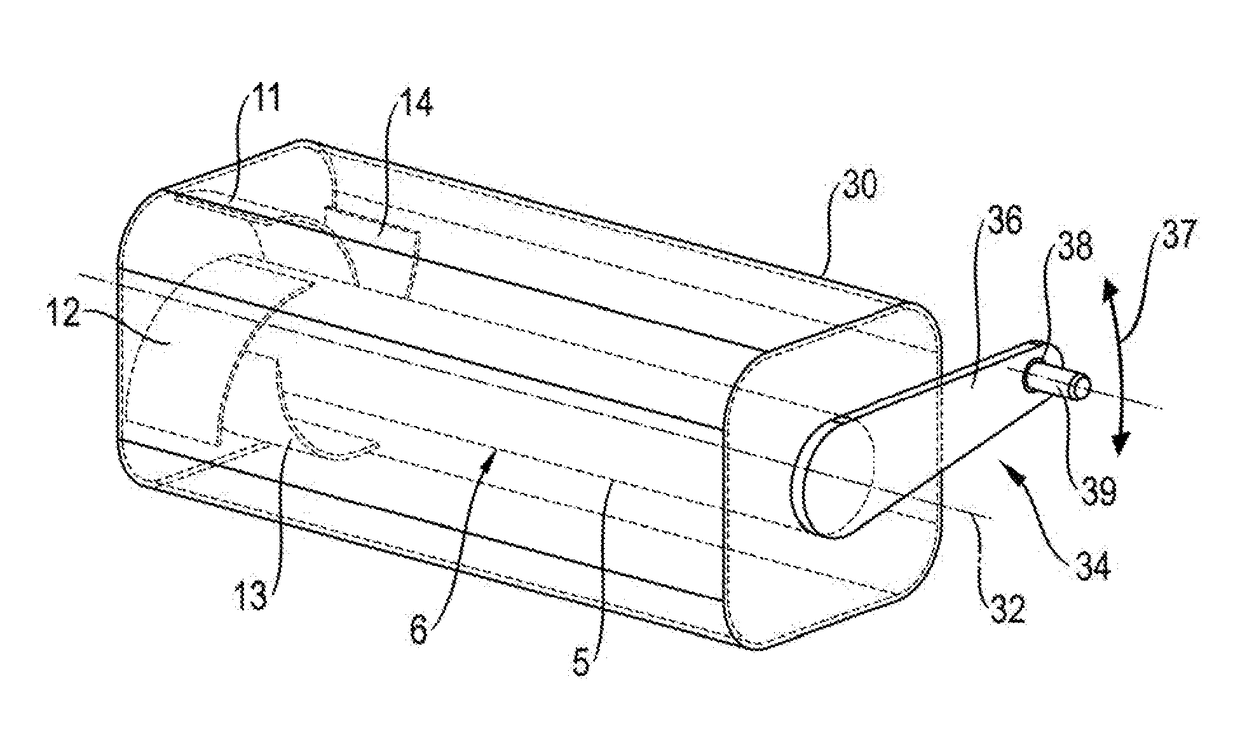
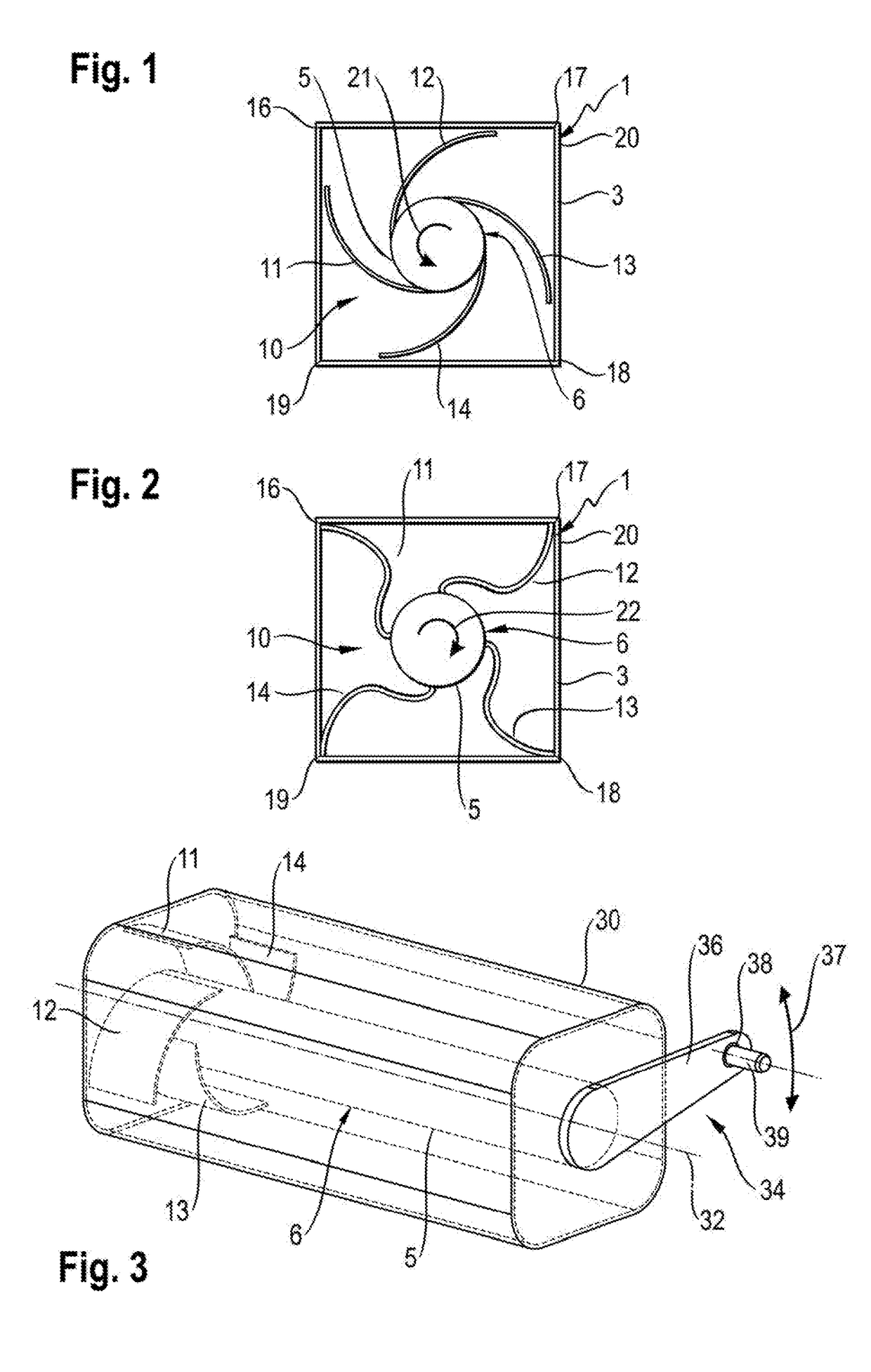
[0022]FIGS. 1 and 2 show an elongate carrier 1 in cross section. The elongate carrier 1 is configured as a hollow profile 3 with a rectangular cross section. The elongate carrier 1 is, for example, a sill of a motor vehicle.
[0023]A tubular fluid container 5 is arranged in the elongate carrier 1. The tubular fluid container 5 is, for example, likewise configured as a hollow profile with a circular cross section.
[0024]The tubular fluid container 5 is a fluidic pressure accumulator 6, in particular a hydraulic pressure accumulator. The pressure accumulator 6 serves to store fluidic energy, in particular hydraulic energy.
[0025]The tubular fluid container 5 can be positioned in the elongate carrier 1 with the aid of a positioning apparatus 10. The positioning apparatus 10 comprises a total of four leaf spring-like spring elements 11 to 14. With the aid of the spring elements 11 to 14, the tubular fluid container 5 can advantageously be mounted in the elongate carrier 1 in a sprung manner.
[0026]The elongate carrier 1 has an angular cross-sectional profile 20. The angular cross-sectional profile 20 is configured in FIG. 1 as a square with four corners 16 to 19.
[0027]In FIG. 1, a free rotational direction is indicated by way of an arrow 21. When the tubular fluid container 5 is rotated in the elongate carrier 1 in its free rotational direction 21, the tubular fluid container 5 can be mounted in the elongate carrier 1 in a simple way.
[0028]During mounting, the tubular fluid container 5 is introduced into the elongate carrier 1 (perpendicularly with respect to the plane of the drawing in FIG. 1). Here, the free ends of the spring elements 11 to 14 are spaced apart from the inner faces of the elongate carrier 1 or slide along them.
[0029]In FIG. 2, a positioning rotational direction is indicated by way of an arrow 22. When the tubular fluid container 5 is rotated in the elongate carrier 1 in the positioning rotational direction 22, the tubular fluid container 5 is particularly advantageously braced in the elongate carrier 1. Here, the free ends of the spring elements 11 to 14 come into frictional contact with the inner faces of the elongate carrier 1. The free ends of the spring elements 11 to 14 particularly advantageously become caught in the elongate carrier 1, advantageously by way of the formation of a positively locking connection.
[0030]By way of rotation of the tubular fluid container 5 in the positioning rotational direction 22, the tubular fluid container 5 is firstly positioned in the elongate carrier 1 in a stable manner. Moreover, the tubular fluid container 5 is mounted in the elongate carrier 1 in a sprung manner. By way of the sprung mounting, the tubular fluid container 5 is decoupled from the elongate carrier 1.
[0031]It can be seen in FIG. 2 that the leaf spring-like spring elements 11 to 14 fold over during the rotation in the positioning rotational direction 22. As a result of the attempt of the spring elements 11 to 14 to extend, the spring elements 11 to 14 become caught with their free ends in the corners 16 to 19 of the square hollow cross-sectional profile 20. As a result, the tubular fluid container 5 is mounted stably in a sprung manner in the elongate carrier 1 in a simple way.
[0032]In the perspective illustration of FIG. 3, the elongate carrier which is denoted by 1 in FIGS. 1 and 2 is indicated by way of a rectangular hollow cross-sectional profile 30. A longitudinal axis of the tubular fluid container 5 is indicated by way of a dash-dotted line 32.
[0033]The hollow cross-sectional profile 30 is square, just like the hollow cross-sectional profile 20 in FIGS. 1 and 2. The square hollow cross-sectional profile 30 in FIG. 3 is configured with rounded corners, however. The catching of the free ends of the leaf spring-like spring elements 11 to 14 is ensured, for example, by way of a corresponding structure, such as a toothing system, of the spring elements 11 to 14 and/or on the inside of the elongate carrier 1.
[0034]Four leaf spring-like spring elements 11 to 14 which correspond to the leaf spring-like spring elements 11 to 14 in FIGS. 1 and 2 are indicated at the left-hand end (in FIG. 3) of the tubular fluid container 5.
[0035]A lever 36 is attached in order to provide a fastening apparatus 34 at the right-hand end (in FIG. 3) of the tubular fluid container 5.
[0036]A double arrow 37 indicates that the tubular fluid container 5 can be rotated via the lever 36 either in the free rotational direction (21 in FIG. 1) or in the positioning rotational direction (22 in FIG. 2). As a result, the rotation during the mounting and/or dismantling of the tubular fluid container 5 is simplified considerably.
[0037]At its free end, the lever 36 has a through hole 38. A fastening means is indicated by way of a line 39, with the aid of which fastening means the lever 36 can be fixed in a desired position.
[0038]The fastening means 39 is, for example, a screw which is plugged through the through hole 38 and is screwed into an associated thread (not shown) on a stationary carrying structure.

PUM

no PUM

Description & Claims & Application Information

We can also present the details of the Description, Claims and Application information to help users get a comprehensive understanding of the technical details of the patent, such as background art, summary of invention, brief description of drawings, description of embodiments, and other original content. On the other hand, users can also determine the specific scope of protection of the technology through the list of claims; as well as understand the changes in the life cycle of the technology with the presentation of the patent timeline. Login to view more.

Similar technology patents

Method for manufacturing a dental prosthesis and an appliance for implantation thereof

InactiveUS7731497B2simplifies positionincrease precision and reliability
Owner:DE MOYER PHILIPPE ALBERT PAUL GHISLAIN

Electrophoretic displays with controlled amounts of pigment

ActiveUS20080266245A1simplifies positionavoids visible artifact
Owner:E INK CORPORATION

Classification and recommendation of technical efficacy words

  • simplifies position

Electrophoretic displays with controlled amounts of pigment

ActiveUS20080266245A1simplifies positionavoids visible artifact
Owner:E INK CORPORATION

Method for manufacturing a dental prosthesis and an appliance for implantation thereof

InactiveUS7731497B2simplifies positionincrease precision and reliability
Owner:DE MOYER PHILIPPE ALBERT PAUL GHISLAIN
Why Eureka
Try Eureka