Electrophoretic displays with controlled amounts of pigment

Active Publication Date: 2008-10-30
E INK CORPORATION
View PDF103 Cites 87 Cited by
  • Summary
  • Abstract
  • Description
  • Claims
  • Application Information

AI Technical Summary

Benefits of technology

[0033]Regardless of the exact method used for its manufacture and the exact type of electrophoretic medium employed, this type of color shutter mode display has the advantages that positioning the color filter with respect to the pixel electrodes is simplified, since the pixel electrodes are readily visible during formation or attachment of the filter, and, more importantly, that the positioning of the color filter adjacent the pixel electrodes avoids visible artifacts which may occur due to parallax when a color filter substantially separated from a backplane (for example, a color filter on the opposed side of the electrophoretic medium from the backplane) is viewed off-axis.
[0034]One problem with such shutter mode microcavity displays is ensuring good contrast ratio, since even in the l

Problems solved by technology

Problems with the long-term image quality of these displays have prevented their widespread usage.
For example, particles that make up electrophoretic displays tend to settle, resulting in inadequate service-life for these displays.
Thus, microcavities in microcavity electrophoretic displays may be irregular.
However, there is relatively little consideration in the published literature relating to other parameters affecting the optical performance of electrophoretic displays, and in particular the amount of pigment needed in the electrophoretic medium.
This is not the case with dual particle electrophoretic displays, and may not be the case with single particle displays using dyes with optical densities higher than those used in most prior art electrophoretic displays.
It has been found that the main factor limiting image stability in electrophoretic displays of the types described in the aforementioned patents and applications is settling of the electrophoretic pigment particles under gravity.
Unfortunately, as is well known to those skilled in the technology of electrophoretic displays, the electrophoretic mobility of the pigment particles (the rate at which the particles move through the liquid phase under a given electric field) is also inversely proportional to the viscosity of the liquid phase, and thus the switc

Method used


Image

  • Electrophoretic displays with controlled amounts of pigment
  • Electrophoretic displays with controlled amounts of pigment
  • Electrophoretic displays with controlled amounts of pigment

Examples


Example

EXAMPLE 1

[0100]An internal phase was prepared comprising 10 percent by volume white particles and 1 percent by volume black particles (carbon black) by volume in a hydrocarbon suspending fluid; the internal phase had a viscosity of 4.75 mPa sec. The white particles comprised titania and had an average size of approximately 0.6 μm and a saturation particle thickness estimated at 1.5 to 2.5 μm. The internal phase was encapsulated in gelatin / acacia microcapsules substantially as described in Paragraphs [0069] to [0074] of U.S. Patent Publication No. 2002 / 0180687. The resultant microcapsules were separated into three batches differing in wet capsule diameter size distributions. Each batch was mixed into a slurry with a polymeric binder, coated to form an electrophoretic film, and laminated to a back electrode to form a switchable display pixel, substantially as described in Paragraphs [0075] and [0076] of the aforementioned 2002 / 0180687. During the coating process, suitable equipment se...

Example

EXAMPLE 2

[0122]This Example illustrates that the addition of PIB to the suspending fluid in Medium A produces an increase in image stability greater than that attributable to the increase in viscosity caused by the PIB addition.

[0123]A preliminary series of experiments were conducted to determine the effect on the viscosity of the 1:1 w / w Isopar / Halocarbon mixture used in Media A and B. This mixture itself was found to have a viscosity of approximately 0.0021 Pa sec at 25° C., and the addition of the pigments used in Media A and B only slightly increased this viscosity.

[0124]The accompanying FIG. 4 shows the variation of relative viscosity (ηrel), that is, the ratio of the solution viscosity to that of 1:1 w / w Isopar / Halocarbon mixture, with weight fraction of PIB (XPIB) in the solution, this variation being of the expected form; the “best fit” curve is a cubic polynomial fit to the data, except that higher XPIB values not plotted in FIG. 4 were included in the data used to determin...

Example

EXAMPLE 3

[0130]This Example illustrates that the addition of PIB to the suspending fluid in Medium B produces an increase in image stability greater than that attributable to the increase in relative viscosity caused by the PIB addition.

[0131]The PIB and Isopar V addition experiments of Example 2 were repeated with Medium B, except that 15 V switching pulses were used, this being the switching voltage for which Medium B was designed. The results are shown in the accompanying FIG. 6, from which it will be seen that the results achieved with Medium B are qualitatively similar to those achieved with Medium A, as described in Example 2 above, except that the reflectance persistence enhancement provided with PIB only occurs at higher concentrations (greater than about 1.1 percent by weight) with Medium B.


PUM


Abstract

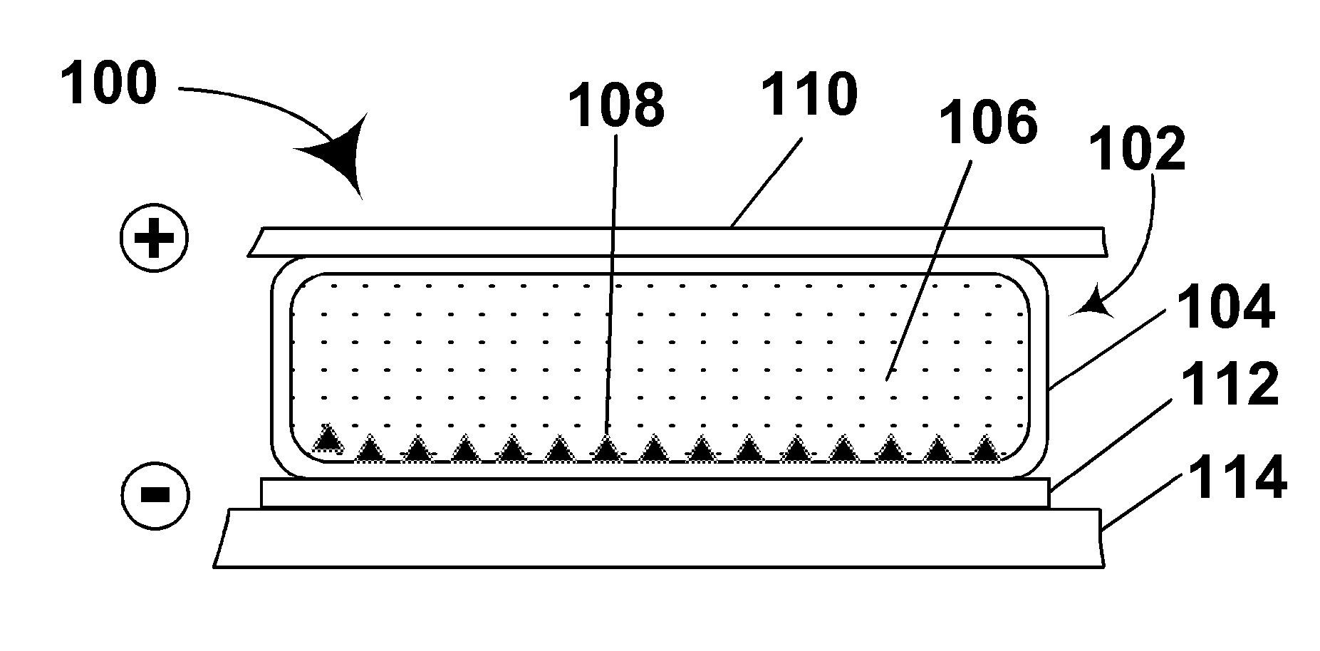
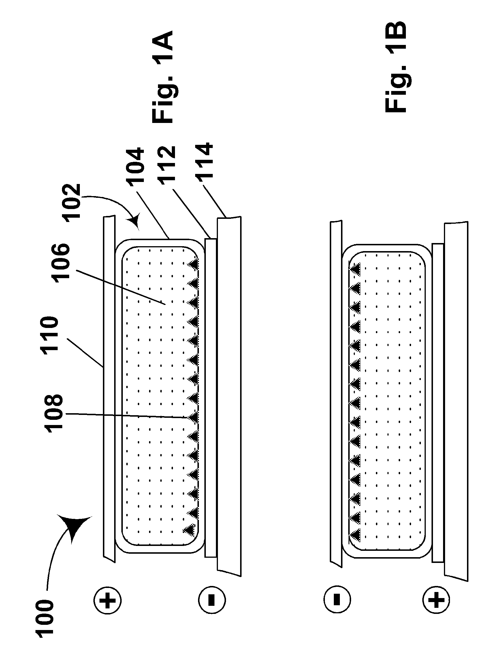
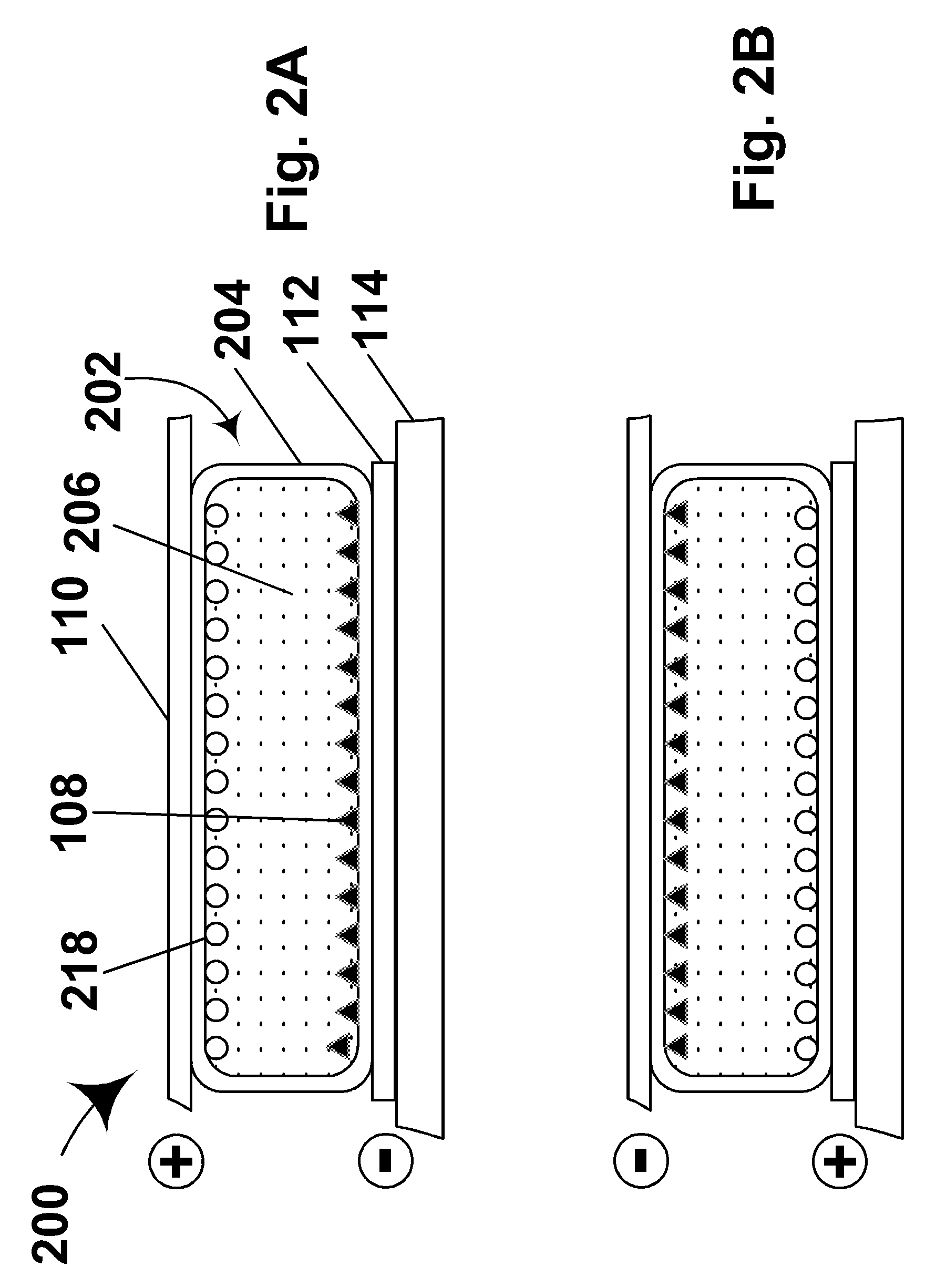
An electrophoretic medium has walls defining a microcavity containing an internal phase. This internal phase comprises electrophoretic particles suspended in a suspending fluid and capable of moving therethrough upon application of an electric field to the electrophoretic medium. The average height of the microcavity differs by not more than about 5 μm from the saturated particle thickness of the electrophoretic particle divided by the volume fraction of the electrophoretic particles in the internal phase.

Description

REFERENCE TO RELATED APPLICATIONS[0001]This application is a continuation-in-part of copending application Ser. No. 10 / 837,062, filed Apr. 30, 2004 (Publication No. 2005 / 0012980), which claims benefit of Provisional Application Ser. No. 60 / 320,158, filed May 2, 2003, and of Provisional Application Ser. No. 60 / 320,169, filed May 6, 2003.[0002]This application is also a continuation-in-part of copending application Ser. No. 11 / 625,907, filed Jan. 23, 2007 (Publication No. 2007 / 0146310). Application Ser. No. 11 / 625,907 is itself a continuation-in-part of application Ser. No. 10 / 063,236, filed Apr. 2, 2002 (now U.S. Pat. No. 7,170,670, issued Jan. 30, 2007), which claims benefit of Application Ser. No. 60 / 280,951, filed Apr. 2, 2001. Application Ser. No. 11 / 625,907 is also a continuation-in-part of application Ser. No. 10 / 711,829, filed Oct. 7, 2004 (now U.S. Pat. No. 7,230,750, issued Jun. 12, 2007), which claims benefit of Application Ser. No. 60 / 481,486, filed Oct. 8, 2003; Applicati...

Claims


Application Information

Patent Timeline
IPC IPC(8): G09G3/34G02F1/167
CPCG02F1/167G02F2001/1672G02F1/1681
Inventor WILCOX, RUSSELL J.CAO, LANDANNER, GUY M.PAOLINI, RICHARD J.WEBBER, RICHARD M.
Owner E INK CORPORATION
Why Eureka
Try Eureka