Shift actuators, differential lock, distributor gearbox, shift gearbox and axle connection

Active Publication Date: 2019-12-26
ZF FRIEDRICHSHAFEN AG
View PDF0 Cites 0 Cited by
  • Summary
  • Abstract
  • Description
  • Claims
  • Application Information

AI Technical Summary

Benefits of technology

[0029]It is provided in accordance with an additional, preferred embodiment of the invention that the shift piston has two different, stepped radial outer circumferences. It simplifies the positioning of the shift piston in the transfer gearbox, in the shift transmission, or in the axle connection, because the shift piston during the installation can be inserted into the opening provided for the

Problems solved by technology

This saves structure s

Method used


Image

  • Shift actuators, differential lock, distributor gearbox, shift gearbox and axle connection
  • Shift actuators, differential lock, distributor gearbox, shift gearbox and axle connection
  • Shift actuators, differential lock, distributor gearbox, shift gearbox and axle connection

Examples


Example

[0042]Same parts, functional units, and comparable components are marked with the same reference characters in all drawings. These parts, functional units and comparable components are, based on their technical characteristics, identically presented, unless the description mentions anything different explicitly or implicitly.

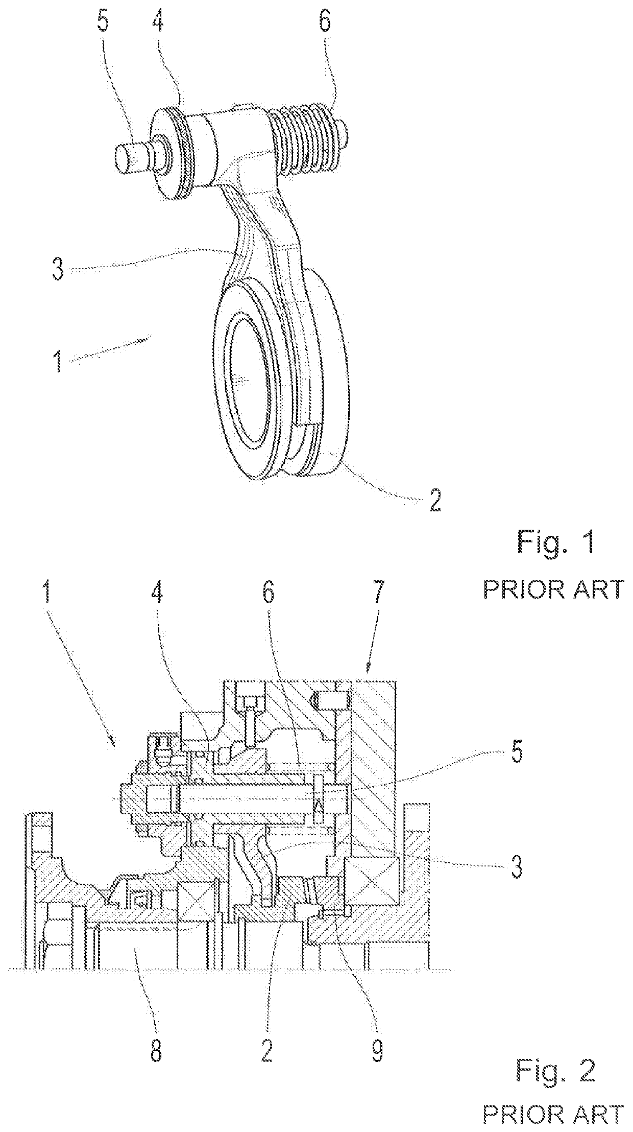
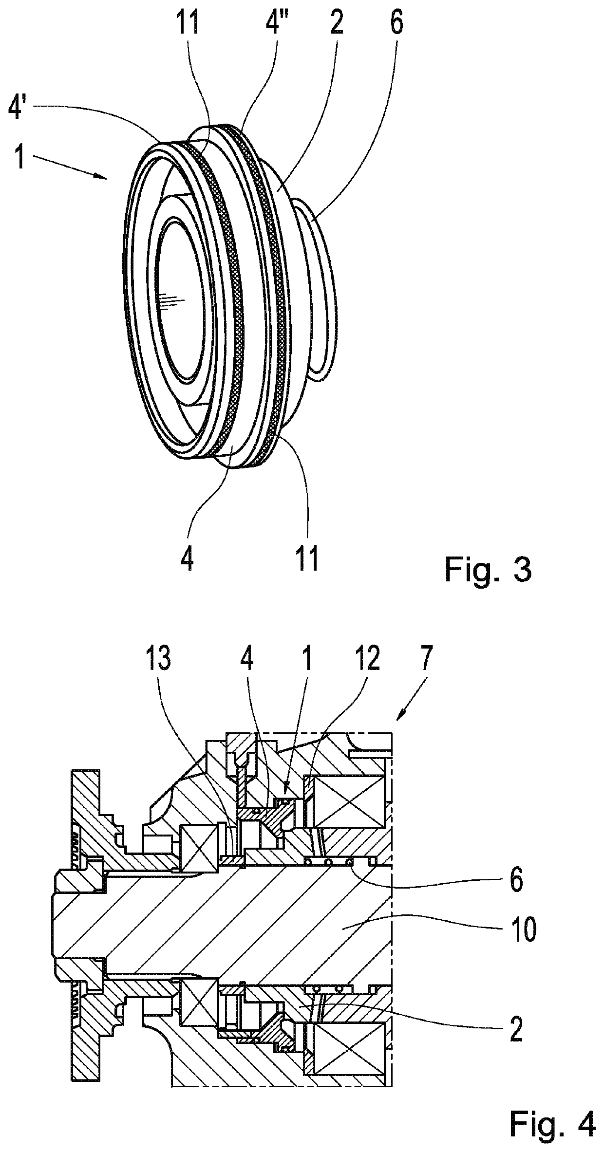
[0043]FIG. 1 shows exemplary and schematically a known shift module 1, comprising of a shift sleeve 2, a shift fork 3, a shift piston 4, a shift rod 5, as well as a resetting element 6. The shift piston 4 is positioned in a not-shown shift cylinder which allows actuation of the shift piston 4 by means of pneumatic pressure, meaning axial shifting of the shift piston 4 on the shift rod 5. The pressurization takes place against a restoring force of the resetting element 6, which is formed, for example, as a helical spring 6. Since the shift piston 4 and the shift fork 3 are mechanically rigidly connected, the shift fork 3 follows the axial shifting of the shift pi...


PUM


Abstract

A shift module (1) for a differential lock (7), a shift gearbox or an axle connection. The shift module has a shift sleeve (2) and a shift piston (4) which is designed as a ring piston (4). The shift module is mounted in one of a respective differential lock, a respective distribution gearbox, and a respective axle connection.

Description

[0001]This application is a National Stage completion of PCT / EP2018 / 050022 filed Jan. 2, 2018, which claims priority from German patent application serial no. 10 2017 201 411.3 filed Jan. 30, 2017.FIELD OF THE INVENTION[0002]The invention concerns a shift actuator for a differential lock, for a shift gearbox, or for an axle connection, as well as a respective differential lock, a respective distributor gearbox, a respective shift gearbox and a respective axle connection.BACKGROUND OF THE INVENTION[0003]Known through the state of the art are differential locks which are in particular used in drive trains of motor vehicles. These differential locks allow, through a blocking of the distribution function of the respective differential gearbox, an even distribution of the drive torque at the drive in axles or the driven vehicle wheels, respectively, which can in particular in rough terrain make the driving easier. Also, axle connections are known which enable the drive or drag of selecte...

Claims


Application Information

Patent Timeline
IPC IPC(8): F16H48/32F16H63/30F16H61/30
CPCF16H61/30F16H48/32F16H63/3023F16D25/082F16D11/10
Inventor PFEFFER, ANDREASREITINGER, FRANZ
Owner ZF FRIEDRICHSHAFEN AG
Why Eureka
Try Eureka