Self-locking descender

a descender and self-locking technology, applied in the field of self-locking descenders, can solve the problems of escaping the handle, losing the mechanical connection with the cam, and using a number of tools which may unintentionally interact with the descender, and achieve the effect of convenient use and reliable descender

Active Publication Date: 2018-06-07
ZEDEL CORP
View PDF5 Cites 2 Cited by
  • Summary
  • Abstract
  • Description
  • Claims
  • Application Information

AI Technical Summary

Benefits of technology

[0016]The object of the invention is to provide a self-locking descender which is easier to use in order to make the descender more reliable.

Problems solved by technology

When the rope access technician is working at his work station, he uses a number of tools which may unintentionally interact with the descender.
In other words, the user applies a pressure on the handle to modulate the friction against the rope, and if the user reaches a threshold value for which the friction force may be insufficient to descend in complete safety, the handle escapes and loses the mechanical connection with the cam.
However, such a solution is not satisfactory as this does not reduce the risk of having a piece of equipment which interacts with the handle of the descender causing an involuntary descent.

Method used


Image

  • Self-locking descender
  • Self-locking descender
  • Self-locking descender

Examples


Embodiment Construction

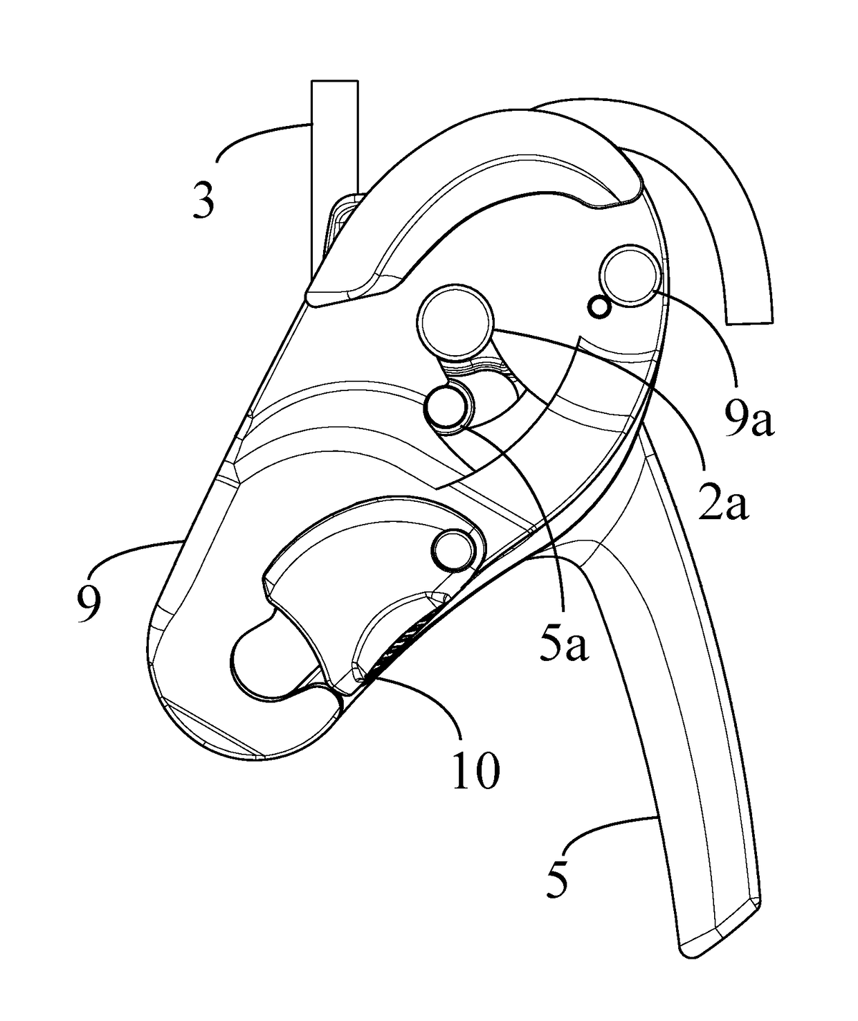
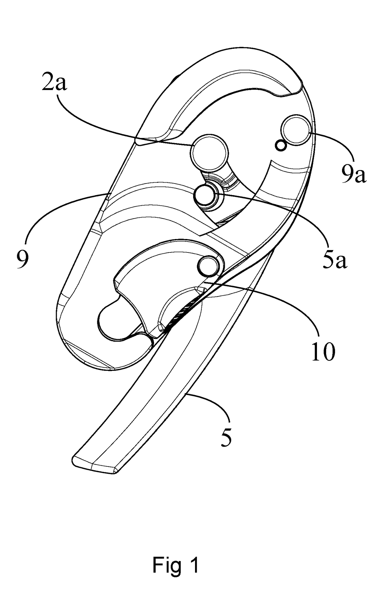
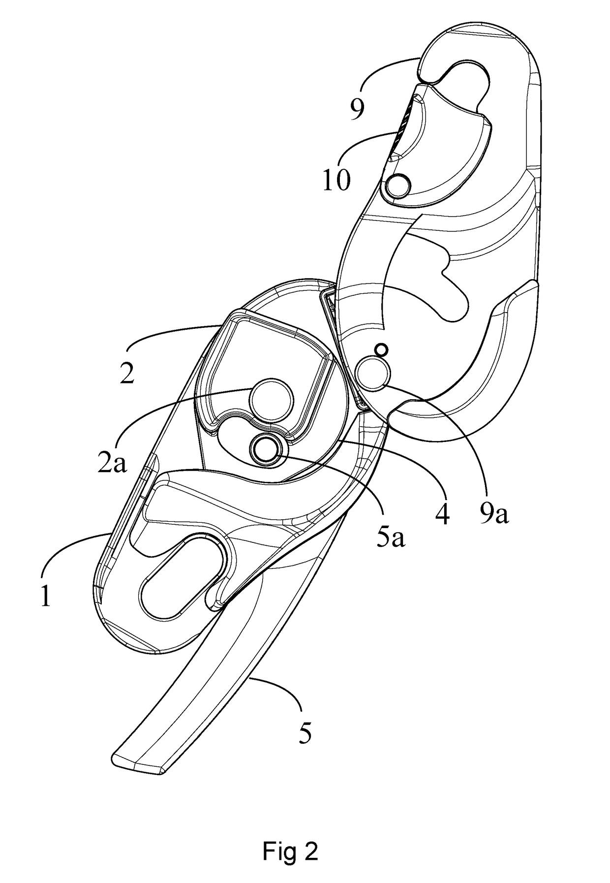
[0045]As illustrated in FIGS. 1 to 8, the self-locking descender comprises a first flange 1 and a cam 2 which is mounted on the first flange 1. The cam 2 is mounted movable on the first flange 1 and in preferential manner movable in rotation which facilitates manufacturing of the descender and use of the cam 2. However, as an alternative, it is possible to provide for the movement of the cam 2 with respect to the first flange 1 to be different from a rotation or to comprise a rotation and another movement. In the illustrated embodiment, the cam 2 is mounted movable around the swivel pin 2a. As illustrated in the different figures, the first flange 1 defines a running path of the rope 3 by means of a side wall so that the rope 3 runs around the cam 2, more precisely between the cam 2 and the side wall of the first flange 1.

[0046]In its movement, the cam 2 moves successively between a first cam position, a second cam position called clamping position of the rope 3, and a third cam pos...


PUM


Abstract

A rope self-locking descender has a first flange, a cam movable with respect to the first flange successively between a first position, a clamping position of the rope and a running position of the rope in the first flange, a handle movable with respect to the first flange successively between a stowing position, a first position of use clamping the rope and a running position of the rope. A first spring is connected to the first flange and to the handle to return the handle to the stowing position. The cam is mechanically connected to the handle in intermittent manner so that movement of the cam from the first position to its clamping position of the rope results in movement of the handle from its stowing position to the first position of use. The handle is not mechanically connected to the cam between the first position and a running position.

Description

BACKGROUND OF THE INVENTION[0001]The invention relates to a self-locking descender on a rope.[0002]The invention also relates to a method for using such a self-locking descender.STATE OF THE ART[0003]When performing rope access work, the rope access technician moves along a rope between different work stations. In conventional manner, the rope access technician descends along the rope until he reaches his work station. The rope access technician then clamps the rope inside the descender so as to be able to perform the different operations related to the work station.[0004]As the rope access technician is installed at height, it is necessary to proceed carefully in order not to compromise his safety by releasing clamping of the rope.[0005]In conventional manner, the descender comprises a clamping position where the rope is clamped inside the descender. This position is used when the rope access technician is at his work station. The descender also comprises a descent position in whic...

Claims


Application Information

Patent Timeline
Patent Type & Authority Applications(United States)
IPC IPC(8): A62B1/14
CPCA62B1/14A62B1/10A62B1/18
Inventor CHABOD, PIERRE-OLIVIERQUILLARD, CHRISTOPHE
Owner ZEDEL CORP
Why Eureka
Try Eureka