
Turbine blade comprising a cavity with wall surface discontinuities and process for the production thereof

a turbine blade and cavity technology, applied in the direction of engine fuction, climate sustainability, air transport, etc., can solve the problems of blade vibration, and achieve the effect of stabilizing

Active Publication Date: 2018-06-07
MTU AERO ENGINES GMBH
View PDF19 Cites 6 Cited by
  • Summary
  • Abstract
  • Description
  • Claims
  • Application Information

AI Technical Summary

Benefits of technology

The patent is about a new way to make blades that reduces the risk of issues like flow of hot gases and sulfidation. This method also creates a bigger space for the material to enter during the casting process. This leads to a more stable and successful blade production process.

Problems solved by technology

During operation of the turbomachine, blades are induced to vibrate, in particular because of unsteady interactions with the working fluid of the turbomachine.

Method used


Image

  • Turbine blade comprising a cavity with wall surface discontinuities and process for the production thereof
  • Turbine blade comprising a cavity with wall surface discontinuities and process for the production thereof
  • Turbine blade comprising a cavity with wall surface discontinuities and process for the production thereof

Examples


Embodiment Construction

[0037]The particulars shown herein are by way of example and for purposes of illustrative discussion of the embodiments of the present invention only and are presented in the cause of providing what is believed to be the most useful and readily understood description of the principles and conceptual aspects of the present invention. In this regard, no attempt is made to show details of the present invention in more detail than is necessary for the fundamental understanding of the present invention, the description in combination with the drawings making apparent to those of skill in the art how the several forms of the present invention may be embodied in practice.

[0038]In the drawings elements that are the same are provided with the same reference numbers.

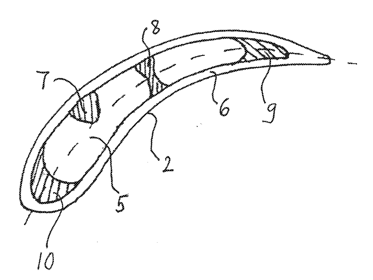
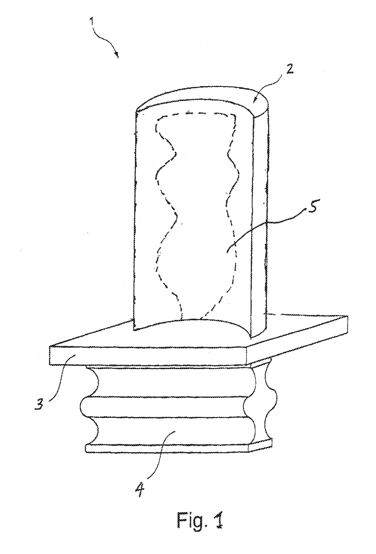
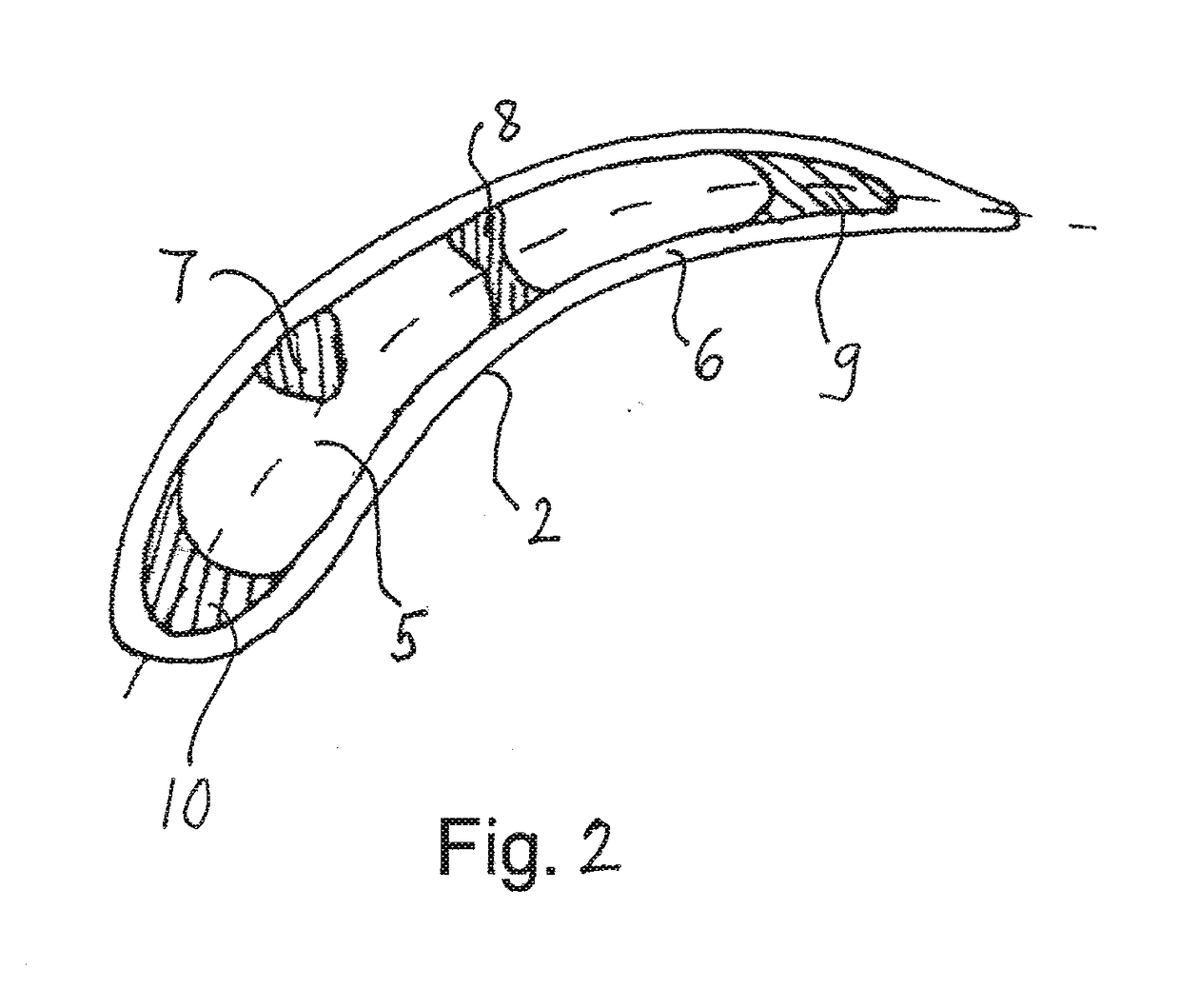
[0039]FIG. 1 schematically illustrates a turbine blade 1 which consists of a (hollow) blade leaf (airfoil) 2 and a blade root 13 with a platform which carries the blade leaf and a connection 4 for connecting the blade to the hub o...


PUM

PropertyMeasurementUnit
Thicknessaaaaaaaaaa
Surfaceaaaaaaaaaa
Heightaaaaaaaaaa

Abstract

The invention relates to a turbine blade which comprises at least one cavity that is defined by a wall with one or more surface discontinuities preferably selected from elevations, depressions and undercuts. The blade may suitably be produced by a generative production method.

Description

BACKGROUND OF THE INVENTION1. Field of the Invention[0001]The present invention relates to a turbine blade or vane and in particular, a blade or vane for a turbomachine such as a gas turbine, as well as to a process for the production of such a blade or vane.2. Discussion of Background Information[0002]In gas turbines with axial flow such as aircraft engines, guide blades (in the following, blades and vanes will collectively be referred to as “blades”) and moving blades are usually situated in alternation one after the other in a housing in the compressor and turbine stages. Moving blades form the moving and rotating part of the gas turbine via which the flowing operating medium is either compressed or depressurized. With the aid of guide blades, the flow created by the moving blades may be forwarded in a defined manner.[0003]Because of their material elasticity, blades have natural modes or eigenmodes. Modes are understood here in a conventional manner to mean natural frequencies a...

Claims


Application Information

Patent Timeline
IPC IPC(8): F01D5/14F01D5/18F01D9/04
CPCF01D5/147F01D5/18F01D9/041F05D2230/31F05D2220/32F05D2300/177F05D2240/126F05D2240/301F05D2300/174F01D5/16F05D2260/961Y02T50/60
Inventor KRAUS, JUERGENKLINGELS, HERMANNFELDMANN, MANFRED
Owner MTU AERO ENGINES GMBH
Learn More