PCB electroplating and electrical connection box structure and modular luminaire

Inactive Publication Date: 2018-06-07
POON CHI WAI PATRICK
View PDF1 Cites 3 Cited by
  • Summary
  • Abstract
  • Description
  • Claims
  • Application Information

AI Technical Summary

Benefits of technology

[0032]The modular lamp is provided with the plurality of light-emitting modules, the shapes of the light-emitting modules are flexible and variable, each module is designed independently, and after the light-emitting modules have been joined together, adjacent light-emitting modules are electrically connected via the conductive strips on the outer side walls and may be combined to form a variety of shapes. The present invention is simple in operation, and strong in combination operability.
[0033]And, each set of conductive strip cont

Problems solved by technology

The connection between electroplating frame of traditional modular lamp and PCB usually adopts bonding wire on energizing platinum-copper of PCB and fixing screw in

Method used


Image

  • PCB electroplating and electrical connection box structure and modular luminaire
  • PCB electroplating and electrical connection box structure and modular luminaire
  • PCB electroplating and electrical connection box structure and modular luminaire

Examples


Example

Embodiment 1

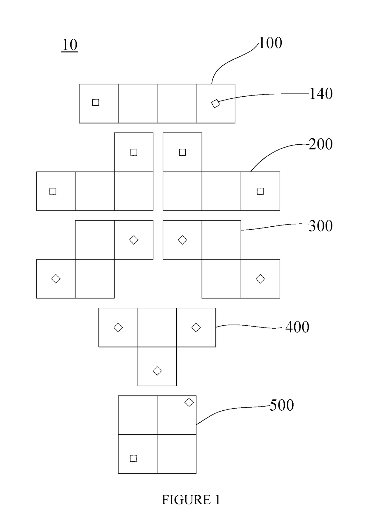
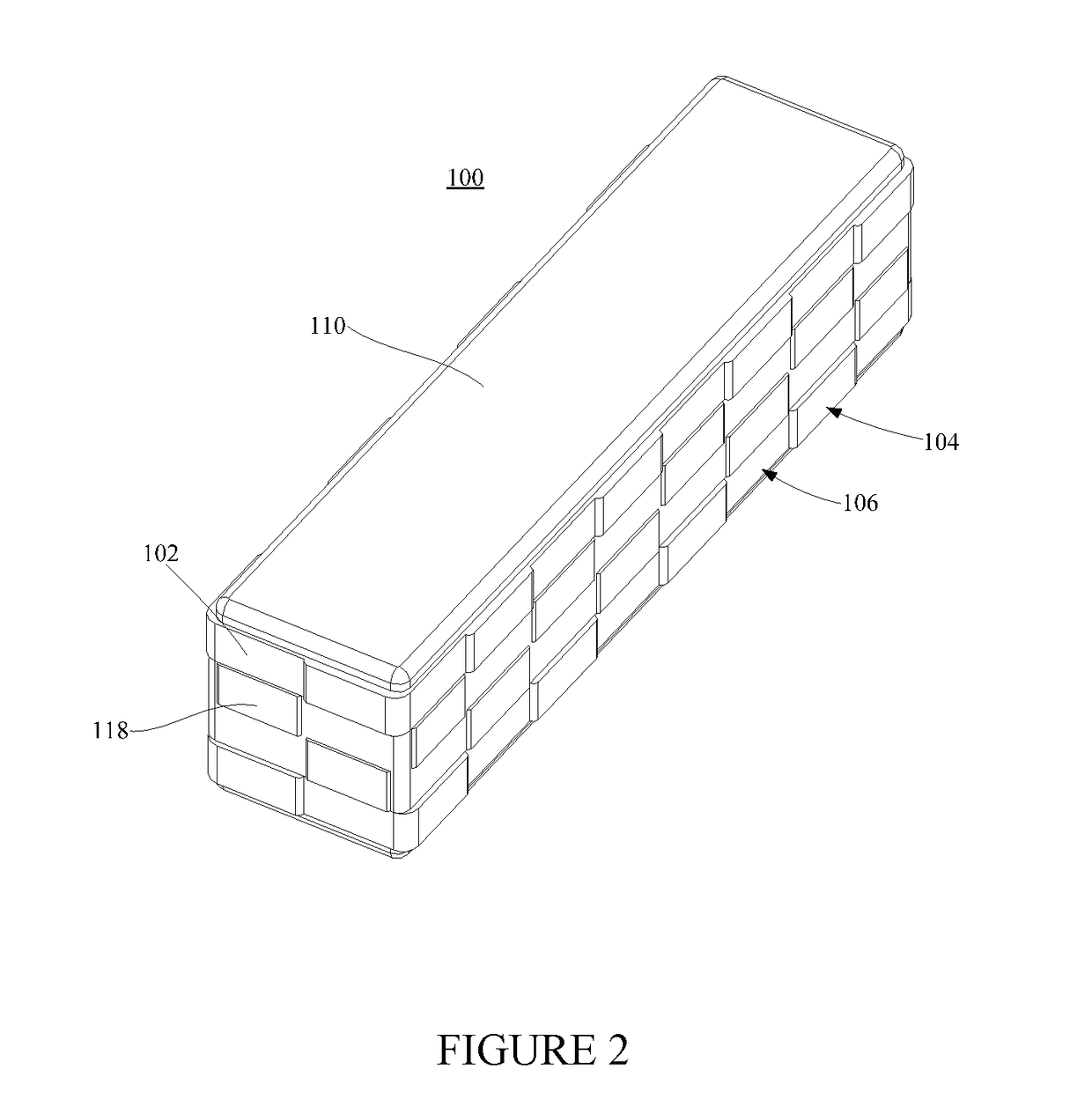
[0062]As shown in FIG. 1, the modular lamp 10 in implementation 1 comprises seven light-emitting modules, in which there is one “line” shape light-emitting module 100; two “L” shape light-emitting modules 200, two “Z” shape light-emitting modules 300, one “T” shape light-emitting module 400 and one “square” shape light-emitting module 500. Each light-emitting module in implementation 1 comprises four square sub-modules assembling in one plate, and the sides of adjacent sub-modules overlap to make the shapes of plurality of light-emitting module respectively correspond with that of plurality of base modules (five base modules) of standard Tetris, in which “line” shape light-emitting module 100 is main module.

[0063]The said sub-modules are only used for explaining the external shapes of each light-emitting module, but not limited to the detail composition of each light-emitting module, which means in implementation 1, the external shape of each light-emitting module can be...

Example

Embodiment 2

[0099]In implementation 1, the conductive strips of each light-emitting module is discontinuous structure, which is set with sub-conductive strip and insulation gap at interval. As shown in FIG. 14, in implementation 2, the conductive strip 21 is continuous structure, the continuous conductive strip 21 forms conductive bands on outer side wall of the housing 22. The FIG. 14 is the structural diagram of “line” shape main module 20, except conductive strip 21, other structures is similar to that of main module in implementation 1. The inner structure of light-emitting module in other shapes is also similar to that of this implementation, unless the external conductive strip is continuous structure.

[0100]Each light-emitting module with continuous conductive strips can freely joint and assemble into different shapes or form different shapes on the same plate.

[0101]Besides, in other implementations, as shown in FIG. 15, the base plate and roof of “square” shape light-emitting...


PUM


Abstract

The present invention relates to an electrical connection structure for a PCB and an electroplating frame, and a modular lamp. The modular lamp comprises a plurality of light-emitting modules. Each light-emitting module comprises a housing and a lamp plate arranged within the housing, a light source and conductive connectors electrically connected to the light source being arranged on the lamp plate, an outer side wall of the housing being provided with two sets of conductive strips surrounding the outer side wall and protruding from the outer side wall, the two sets of conductive strips being respectively electrically connected to two electrodes of the lamp plate via the conductive connectors. After the plurality of light-emitting modules have been assembled and joined together, adjacent light-emitting modules are in contact and electrically connected via the conductive strips. The modular lamp is provided with the plurality of light-emitting modules, the shapes of the light-emitting modules are flexible and variable, each module is designed independently, and after the light-emitting modules have been joined together, adjacent light-emitting modules are electrically connected via the conductive strips on the outer side walls and may be combined to form a variety of shapes. The present invention is simple in operation, and strong in combination operability.

Description

RELATED APPLICATION[0001]This application is the US national phase of International Application Number PCT / CN2016 / 090987, Filed on 22 Jul. 2016, which designated the U.S. and which claims benefit of CN201520575049.X filed 31 Jul. 2015, the entire content of which is hereby incorporated by reference.FIELD OF THE INVENTION[0002]The present invention relates to lamps and lanterns field, especially electrical connection structure for a PCB and an electroplating frame, and a modular lamp.BACKGROUND OF THE INVENTION[0003]The modular lamp is popular among masses of customers for its features of self-assembly shapes. The connection between electroplating frame of traditional modular lamp and PCB usually adopts bonding wire on energizing platinum-copper of PCB and fixing screw into boss of electroplating frame, which is inefficient in assembly, costly and not easy to assemble, and the bonding wire blocks partial light effecting light effect.SUMMARY OF THE INVENTION[0004]In view of this, it's...

Claims


Application Information

Patent Timeline
IPC IPC(8): F21S2/00F21V19/00F21V23/06F21V23/04F21S9/02F21V17/12F21V21/096H05K1/18
CPCF21S2/005F21V19/0025F21V23/06F21V23/04F21S9/02F21V17/12F21V21/096H05K1/18F21Y2115/10H05K2201/10113H05K2201/10106H05K2201/032F21V15/01F21V19/003F21V21/005F21S2/00
Inventor PATRICK
Owner POON CHI WAI PATRICK
Why Eureka
Try Eureka