Moving head lamp

Inactive Publication Date: 2018-06-07
SGM
View PDF18 Cites 2 Cited by
  • Summary
  • Abstract
  • Description
  • Claims
  • Application Information

AI Technical Summary

Benefits of technology

[0007]On this background it is the object of the present invention to provide a movi

Problems solved by technology

The lamps are therefore often quite bulky and heavy and therefore difficult to handle.
This position, however, is often far below the centre of gravity of the moving head lamps, and is therefore increasing risk that t

Method used


Image

  • Moving head lamp
  • Moving head lamp
  • Moving head lamp

Examples


Embodiment Construction

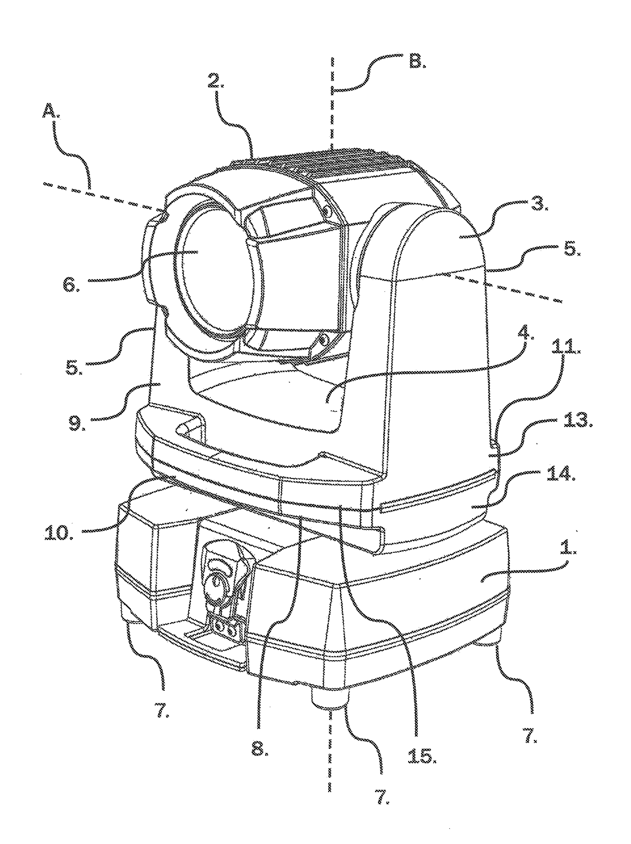
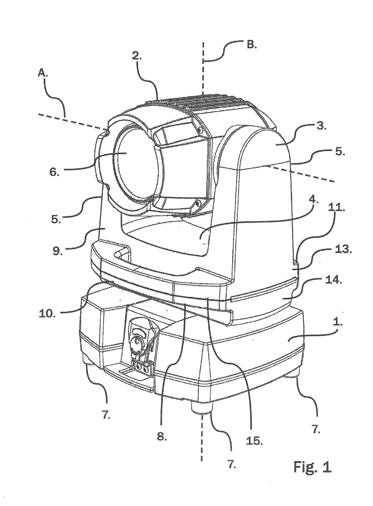
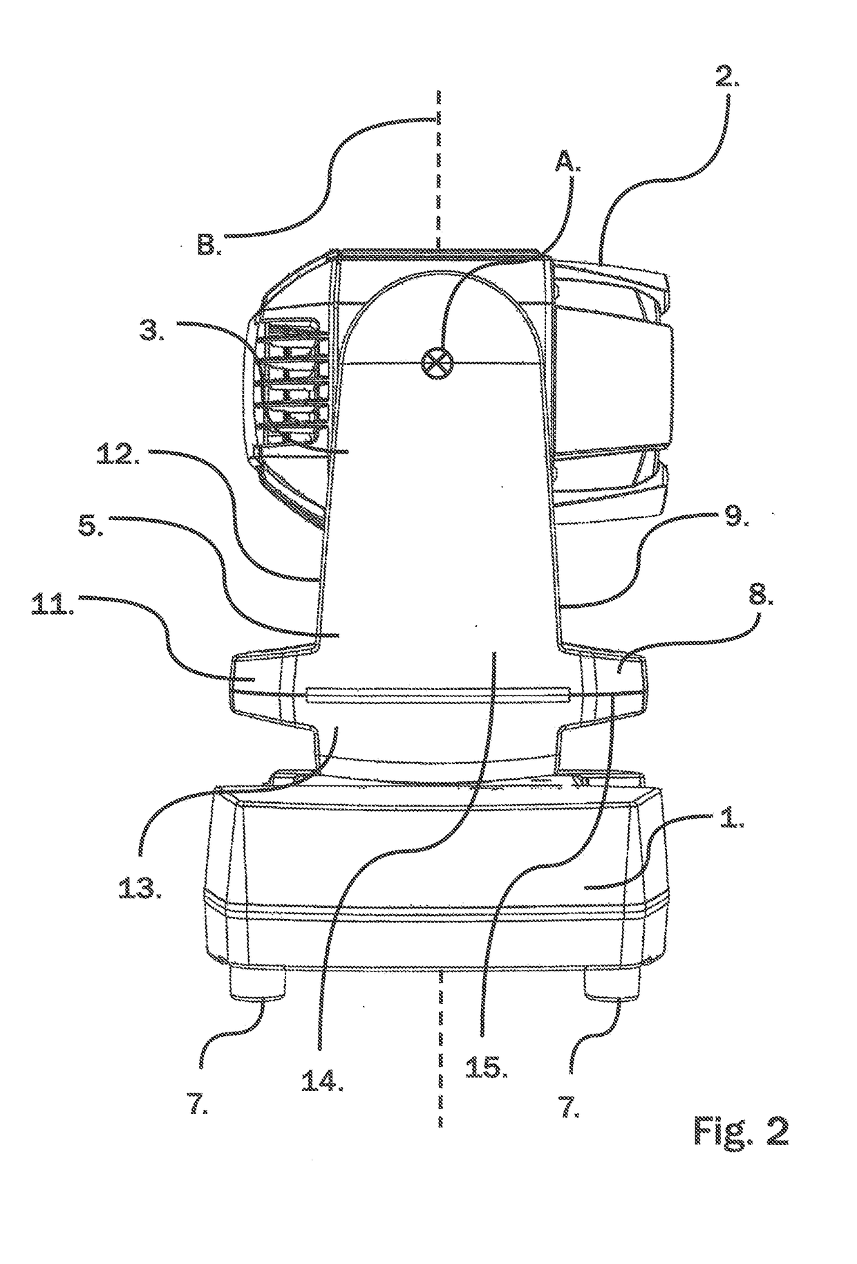
[0022]Thus, FIGS. 1 and 2 shows the same moving head lamp having a lamp base 1 with a set of feet 7 allowing it to rest on a plane support, a lamp head 2 and a yoke 3 having a mid-section 4 and two legs 5 extending upwardly from the mid-section 4. The lamp head 2 is tiltable with respect to the yoke 3 about the axis (second axis) A shown on the figure, and it contains at least a light source for projecting a light beam out of the opening 6 formed by an optical element 6 which might be replaced e.g. by another light source such as an LED array or other lighting arrangement providing a beam of light concentrated in a selected direction.

[0023]The yoke 3 hereby carries the lamp head 2 and as the yoke 3 is mounted on the lamp base 1 so that it can rotate (pan) about the axis (first axis) B shown on the figure, then it is possible to direct the light beam provided by the lamp head 2 in any direction only limited by the physical and mechanical structure of the moving head lamp 1.

[0024]For ...


PUM


Abstract

A moving head lamp comprising: a lamp base adapted for resting on a 5 plane surface and/or for being mounted on a separate structure; a lamp head carrier having a first end being rotatably mounted about a first axis of rotation in relation to the lamp base; a lamp head with a light source, the lamp head being rotatably mounted about a second axis in relation to the lamp head carrier, said second axis being different from, and preferably 10 substantially perpendicular to, said first axis; and a first carrying handle arranged on the lamp head carrier between the lamp head and the lamp base, wherein said carrying handle comprises an elongate grip section extending in its longitudinal direction substantially parallel to said second axis.

Description

FIELD OF USE OF THE INVENTION[0001]The present invention relates to moving head lamps, and more particularly to a moving head lamp comprising a lamp base adapted for resting on a surface and / or for being mounted on a separate structure, a lamp head carrier having a first end being is rotatably mounted about a first axis of rotation (the panning axis) of rotation in relation to the lamp base and a lamp head with a light source, the lamp head being rotatably mounted about a second axis of rotation (the tilting axis) in relation to the lamp head carrier, said second axis being different from, and preferably substantially perpendicular to, said first axis, and where the moving head lamp further comprises one or more handles arranged for manually lifting and moving the moving head lamp.STATE OF THE ART[0002]Moving head lamps of the above mentioned kind are mostly used for providing directed illumination at various venues such as shows, concerts and exhibitions, where they are frequently ...

Claims


Application Information

Patent Timeline
IPC IPC(8): F21V21/40F21V21/30F21V21/15F21W131/406
CPCF21V21/406F21V21/15F21V21/30F21W2131/406F21S6/004F21S9/02F21V21/40
Inventor JOHANSEN, PETER
Owner SGM
Why Eureka
Try Eureka